NIST SPECIAL PUBLICATION 1800-3C
Attribute Based Access Control
Volume C:
How-to Guides
Bill Fisher
National Cybersecurity Center of Excellence
National Institute of Standards and Technology
Norm Brickman
Prescott Burden
Santos Jha
Brian Johnson
Andrew Keller
Ted Kolovos
Sudhi Umarji
Sarah Weeks
The MITRE Corporation
McLean, VA
September 2017
SECOND DRAFT

DISCLAIMER
Certain commercial entities, equipment, products, or materials may be identified in this document in order to describe an experimental procedure or concept adequately. Such identification is not intended to imply recommendation or endorsement by NIST or NCCoE, nor is it intended to imply that the entities, equipment, products, or materials are necessarily the best available for the purpose.
National Institute of Standards and Technology Special Publication 1800-3c, Natl. Inst. Stand. Technol. Spec. Publ. 1800-3c, 577 pages, September 2017, CODEN: NSPUE2
FEEDBACK
You can improve this guide by contributing feedback. As you review and adopt this solution for your own organization, we ask you and your colleagues to share your experience and advice with us.
Comments on this publication may be submitted to: abac-nccoe@nist.gov.
Public comment period: September 20, 2017 through October 20, 2017
All comments are subject to release under the Freedom of Information Act (FOIA).
NATIONAL CYBERSECURITY CENTER OF EXCELLENCE
The National Cybersecurity Center of Excellence (NCCoE), a part of the National Institute of Standards and Technology (NIST), is a collaborative hub where industry organizations, government agencies, and academic institutions work together to address businesses’ most pressing cybersecurity issues. This public-private partnership enables the creation of practical cybersecurity solutions for specific industries, as well as for broad, cross-sector technology challenges. Through consortia under Cooperative Research and Development Agreements (CRADAs), including technology partners—from Fortune 50 market leaders to smaller companies specializing in IT security—the NCCoE applies standards and best practices to develop modular, easily adaptable example cybersecurity solutions using commercially available technology. The NCCoE documents these example solutions in the NIST Special Publication 1800 series, which maps capabilities to the NIST Cyber Security Framework and details the steps needed for another entity to recreate the example solution. The NCCoE was established in 2012 by NIST in partnership with the State of Maryland and Montgomery County, Md.
To learn more about the NCCoE, visit https://nccoe.nist.gov. To learn more about NIST, visit https://www.nist.gov.
NIST CYBERSECURITY PRACTICE GUIDES
NIST Cybersecurity Practice Guides (Special Publication Series 1800) target specific cybersecurity challenges in the public and private sectors. They are practical, user-friendly guides that facilitate the adoption of standards-based approaches to cybersecurity. They show members of the information security community how to implement example solutions that help them align more easily with relevant standards and best practices and provide users with the materials lists, configuration files, and other information they need to implement a similar approach.
The documents in this series describe example implementations of cybersecurity practices that businesses and other organizations may voluntarily adopt. These documents do not describe regulations or mandatory practices, nor do they carry statutory authority.
ABSTRACT
Enterprises rely upon strong access control mechanisms to ensure that corporate resources (e.g., applications, networks, systems, and data) are not exposed to anyone other than an authorized user. As business requirements change, enterprises need highly flexible access control mechanisms that can adapt. The application of attribute based policy definitions enables enterprises to accommodate a diverse set of business cases. This NCCoE practice guide details a collaborative effort between the NCCoE and technology providers to demonstrate a standards-based approach to attribute based access control (ABAC).
This guide discusses potential security risks facing organizations, benefits that may result from the implementation of an ABAC system, and the approach the NCCoE took in developing a reference architecture and build. It includes a discussion of major architecture design considerations, an explanation of security characteristic achieved by the reference design, and a mapping of security characteristics to applicable standards and security control families.
For parties interested in adopting all or part of the NCCoE reference architecture, this guide includes a detailed description of the installation, configuration, and integration of all components.
KEYWORDS
access control; access management; attribute provider; authentication; authorization; identity federation; identity management; identity provider; relying party
ACKNOWLEDGMENTS
We are grateful to the following individuals for their generous contributions of expertise and time.
| Name | Organization |
| Nate Lesser | NIST National Cybersecurity Center of Excellence |
| Paul Timmel | NIST National Cybersecurity Center of Excellence |
| Paul Grassi | NIST National Strategy for Trusted Identities in Cyberspace |
| Mike Garcia | NIST National Strategy for Trusted Identities in Cyberspace |
| Naomi Lefkovitz | NIST National Strategy for Trusted Identities in Cyberspace |
| Rene Peralta | NIST National Strategy for Trusted Identities in Cyberspace |
| Dave Ferriaolo | NIST Computer Security Division |
| Vincent Hu | NIST Computer Security Division |
| Roger Wiggenstam | NextLabs Inc |
| John Conduit | NextLabs Inc |
| Srikanth Karanam | NextLabs Inc |
| Adam Madlin | Symantec Corporation |
| Steve Kruse | Symantec Corporation |
| Steve Schmalz | RSA |
| Ben Smith | RSA |
| Andrew Whelchel | RSA |
| Chris Leggett | Ping Identity |
| Paul Fox | Microsoft Corporation |
| Derek Keatley | Microsoft Corporation |
| Hemma Prafullchandra | Hytrust |
| John McLeese | Hytrust |
| Dave Cox | ID/Dataweb |
| Chris Donovan | ID/Dataweb |
| Pete Romness | Cisco |
| Kevin McFadden | Cisco |
| John Eppish | Cisco |
| Chris Ceppi | Situational Corporation |
The Technology Partners/Collaborators who participated in this build submitted their capabilities in response to a notice in the Federal Register. Respondents with relevant capabilities or product components were invited to sign a Cooperative Research and Development Agreement (CRADA) with NIST, allowing them to participate in a consortium to build this example solution. We worked with:
| Technology Partner/Collaborator | Build Involvement |
| Ping Identity | PingFederate Federation Server |
| NextLabs | Entitlements Management Policy Enforcement Point |
| Microsoft | Policy Controller Policy decision point |
| RSA | Control Center Policy Administration Point |
| Symantec | Active Directory |
| Cisco | SharePoint |
List of Figures
Figure 2‑1 Out-of-Band Token Length
Figure 2‑2 Successful List Created
Figure 10‑2 Ping Custom Data Store Interaction Diagram
Figure 10‑3 Ping Custom Data Store Class Diagram
Figure 10‑4 NextLabs PIP Plugin Class Diagram
Figure 10‑5 NextLabs PIP Plugin Interaction Diagram
Figure 10‑6 Communication Between Plugin and Relying Party
Figure 10‑7 Protocol Broker Interaction Diagram
Figure 10‑8 Protocol Broker Class Diagram
List of Tables
Table 2‑1 Persistent User Enrollment
Table 2‑4 Session Sign-In – Low Risk
Table 2‑5 Session Sign-In – Medium Risk
Table 2‑6 Session Sign-In – High Risk
Table 2‑7 Session Sign-In – Critical Risk
1. Introduction
The following guides show IT professionals and security engineers how we implemented this example solution. We cover all of the products employed in this reference design. We do not recreate the product manufacturers’ documentation, which is presumed to be widely available. Rather, these guides show how we incorporated the products together in our environment.
Note: These are not comprehensive tutorials. There are many possible service and security configurations for these products that are out of scope for this reference design.
1.1. Practice Guide Structure
This NIST Cybersecurity Practice Guide demonstrates a standards-based reference design and provides users with the information they need to replicate an Attribute Based Access Control (ABAC) implementation. This reference design is modular and can be deployed in whole or in parts.
This guide contains three volumes:
- NIST SP 1800-11a: Executive Summary
- NIST SP 1800-11b: Approach, Architecture, and Security Characteristics – what we built and why
- NIST SP 1800-3c: How-To Guides – instructions for building the example solution (you are here)
Depending on your role in your organization, you might use this guide in different ways:
Business decision makers, including chief security and technology officers will be interested in the Executive Summary (NIST SP 1800-11a), which describes the:
- challenges enterprises face in access control solutions
- example solution built at the NCCoE
- benefits of adopting the example solution
Technology or security program managers who are concerned with how to identify, understand, assess, and mitigate risk will be interested in this part of the guide, NIST SP 1800-11b, which describes what we did and why. The following sections will be of particular interest:
- Section 4.4.1, Risk, provides a description of the risk analysis we performed
- Section 4.4.3, Security Control Map, maps the security characteristics of this example solution to cybersecurity standards and best practices
You might share the Executive Summary, (NIST SP 1800-11a), with your leadership team members to help them understand the importance of adopting standards-based ABAC implementation.
IT professionals who want to implement an approach like this will find the whole practice guide useful. You can use the How-To portion of the guide, NIST SP 1800-3c, to replicate all or parts of the build created in our lab. The How-To guide provides specific product installation, configuration, and integration instructions for implementing the example solution. We do not recreate the product manufacturers’ documentation, which is generally widely available. Rather, we show how we incorporated the products together in our environment to create an example solution.
This guide assumes that IT professionals have experience implementing security products within the enterprise. While we have used a suite of commercial products to address this challenge, this guide does not endorse these particular products. Your organization can adopt this solution or one that adheres to these guidelines in whole, or you can use this guide as a starting point for tailoring and implementing parts of an ABAC solution. Your organization’s security experts should identify the products that will best integrate with your existing tools and IT system infrastructure. We hope you will seek products that are congruent with applicable standards and best practices. Volume B, Section 4.5, Technologies, lists the products we used and maps them to the cybersecurity controls provided by this reference solution.
A NIST Cybersecurity Practice Guide does not describe “the” solution, but a possible solution. This is a draft guide. We seek feedback on its contents and welcome your input. Comments, suggestions, and success stories will improve subsequent versions of this guide. Please contribute your thoughts to abac-nccoe@nist.gov.
1.2. Build Overview
The following section provides detailed instructions for implementing, configuring and integrating an ABAC solution coupled with identity and attribute federation. These instructions detail an example of an ABAC implementation using a policy enforcement point that is closely coupled with a SharePoint file server and two sources of environmental attributes. Before implementing this reference design, individuals should refer to NIST SP 1800-3b Approach, Architecture, and Security Characteristics to better understand the design decision that we made as part of this implementation.
1.3. Typographical Conventions
The following table presents typographic conventions used in this volume.
| Typeface/Symbol | Meaning | Example | |
|---|---|---|---|
| Italics | filenames and pathnames references to documents that are not hyperlinks, new terms, and placeholders |
For detailed definitions of terms, see the NCCoE Glossary. | |
| Bold | names of menus, options, command buttons and fields | Choose File > Edit. | |
Monospace
|
command-line input, on-screen computer output, sample code examples, status codes | mkdir
|
|
Monospace Bold
|
command-line user input contrasted with computer output | service sshd start
|
|
| blue text | link to other parts of the document, a web URL, or an email address | All publications from NIST’s National Cybersecurity Center of Excellence are available at https://nccoe.nist.gov. | |
2. Setting Up the Identity Provider
This guide details an attribute based access control (ABAC) implementation that leverages identity federation. In a federation model, the identity provider (IdP) authenticates the user requesting access and provides attributes assigned to that user to the relying party (RP). In addition to attributes assigned to the user, the IdP sends environmental and device attributes to the RP. The RP, which controls access to the resource requested by the user, utilizes the identity and attributes information to make runtime decisions to grant or deny access to the user.
In this section, we install and configure federation components at the identity provider. The components in this section facilitate federated, Security Assertion Markup Language (SAML)-based authentication using account credentials in the identity provider’s Microsoft Active Directory Domain Services (referred to as Microsoft AD in this guide). The federated authentication between the RP and IdP is facilitated by Ping Identity’s PingFederate application. This build also requires the user to authenticate with a second factor, which is handled by the RSA adaptive authentication server.
Each of the components used for the build are described in the Components section. Following the Components section are step-by-step instructions for installing, configuring, and integrating the components.
If you follow the instructions in this section, you will be able to perform a Functional Test to verify the successful completion of the steps for installing, configuring, and integrating the components.
2.1. Components
Federated Authentication at the IdP involves the following distinct components:
- Cisco Switch (Catalyst 2960-X Series): Acts as a switch and router in the build, routing traffic from users to the services and applications on another network segment
- Cisco Identity Services Engine (ISE): Authenticates users from other networks or network segments, and provides device and network attributes to the Ping-Federate IdP via the Situational Context Connector
- Microsoft AD: An LDAP directory service that stores user account and attribute information
- Nginx Web Server: A web server installed on a separate host that is required for handling Network Access Device (NAD) redirects for the Situational Context Connector. In this build, we used Nginx.
- PingFederate-IdP: A federation system or trust broker for the IdP
- PingFederate-RP: Serves as the trust broker for SharePoint
- RSA Adaptive Authentication (RSA AA): Requires the user to authentication using a Short Message Service (SMS) message sent to the user’s mobile phone. Collects environmental information about the user and the user’s system or agent at the time of authentication.
- SCE Plug-in: Handles communications between the PingFederate-IdP and the RSA AA
- Situational Context Connector: IdP Adapter for PingFederate that integrates PingFederate with the Cisco Identity Server Engine via the pxGrid Application Programming Interface (API)
2.1.1. Cisco Switch and Cisco Identity Services Engine
The Cisco Catalyst 2960-X Series switch serves as a switching and routing device, primarily for the purpose of routing users’ traffic from one network or network segment to another, where the protected resources and services are located. The Cisco ISE authenticates users whose traffic comes from the switch, and from that authentication provides device and network attributes to the PingFederate IdP via the Situational Context Connector.
2.1.2. Microsoft AD
Microsoft AD acts as a user identity management repository for the IdP. It includes the ability to provision and de-provision user identities; the creation, modification, and deletion of subject attributes; and the provisioning and de-provisioning of subject attributes to specific user identities. In this build, Microsoft AD is the only source for subject attributes from the IdP.
2.1.3. Nginx Web Server
Nginx acts as a web server that handles NAD redirects for the Situational Context Connector. It is used to trigger the NAD (Cisco Switch in this case) to insert the session identification (ID) as a parameter to create a secure browser cookie, which gets returned to PingFederate and then verified by the Context Connector during authentication. When the Context Connector matches the session ID from the secure browser cookie with the session ID from Cisco ISE, federation can continue, and a Security Assertion Markup Language (SAML) response is returned to the browser. Finally, the browser POSTs a SAML response to the PingFederate-RP.
2.1.4. PingFederate-IdP
Ping Identity PingFederate-IdP serves as a federation system or trust broker for the IdP. PingFederate-IdP provides initial user authentication and retrieval of user attributes to satisfy SAML requests from the RP. Once the user has been authenticated, PingFederate-IdP queries subject attributes from AD and environmental attributes from the RSA AA event log. PingFederate-IdP packages both subject and environmental attributes in a SAML 2.0 token to be sent to the RP.
PingFederate Usage Notes:
When using the PingFederate application to perform an administrative configuration, there is usually a sequence of screens that require user entry, ending with a summary page. Once you click Done on the summary page, you must also click Save on the following page to actually save the configurations. If you forget to click Save, you may inadvertently lose changes to the configuration.
In the PingFederate application and associated documentation, the RP is referred to as the Service Provider.
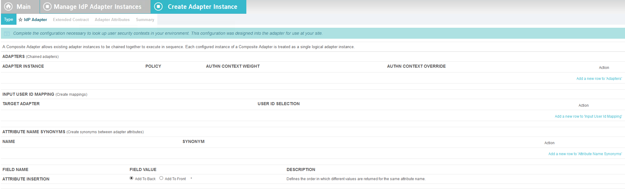
When using the PingFederate application to perform configuration, refer to the title of the tab with a small star icon to its left to identify the item you are currently configuring. For example, if you navigated to the following screen, you would be on the IdP Adapter screen.

2.1.5. PingFederate-RP
Ping Identity PingFederate-RP serves as the trust broker for SharePoint. When the user requires authentication, PingFederate-RP redirects the user to the IdP via a SAML request to get the necessary assertions. Once authenticated, PingFederate-RP arranges for the browser’s Hypertext Transfer Protocol Secure (HTTPS) content to have the proper information in proper format for acceptance at the target resource (SharePoint).
2.1.6. RSA Adaptive Authentication
RSA AA gathers environmental information about the user and the user’s system or agent at the time of authentication. RSA AA collects information such as patch level, operating system, and location, and it generates a risk score associated with the user authentication. A risk score threshold can then be defined in RSA AA, which, if exceeded, can force a user to step up to one of the additional authentication mechanisms. In this build, information collected by RSA AA to generate a risk score is also passed through PingFederate-IdP to the RP side of the operation to be used as environmental attributes. The RSA AA event log contains the transaction ID of each user authentication and the associated environmental information collected by RSA AA at the time of authentication.
2.1.7. SCE Plug-in
The SCE Plug-in handles communications between the PingFederate-IdP and the RSA AA. It is responsible for passing the RSA AA transaction ID for the user authentication that PingFederate-IdP uses to query the RSA AA event log.
2.1.8. Situational Context Connector
The Situational Context Connector is an IdP adapter for PingFederate that integrates PingFederate with the Cisco Identity Server Engine via the pxGrid API. Deploying this solution for PingFederate enables device-level authentication and authorization for web single sign-on (SSO) use cases. When a user attempts a SSO via PingFederate, the Context Connector queries Cisco ISE, retrieves the device context for the end‐user device, and matches device context with the credentials of an authenticated user. The result is a session based on a combination of user and device information. The Context Connector enables real‐time evaluation of Cisco ISE state-of-the-art device profiling. The Context Connector can provide information about the user and the session to the PingFederate IdP, which the PingFederate IdP includes in the SAML token sent to the PingFederate RP. The Context Connector relies on a web server for NAD redirects (implemented with Nginx on a separate server in this build), and a Session Validator that is included in the Situation Context Connector integration kit.
2.1.9. Required or Recommended Files, Hardware, and Software
| Component | Required Files | Recommended or Minimum Hardware Requirements | Hardware Used in this Build | Recommended or Minimum Operating System or Other Software | Operating System or Other Software Used in this Build |
|---|---|---|---|---|---|
| Cisco ISE 2.1 (as Virtual Appliance) | ise-2.1.0.474.SPA.x86_64.iso | 16GB RAM; 6 cores, 2GHz or faster; 200 GB free disk space | 16GB RAM; 4 cores, 2GHz; 200 GB hard disk space | N/A | N/A |
| Microsoft AD | N/A | 512MB RAM; 1.4GHz CPU; 32GB free disk space | 4GB RAM; 2.2GHz CPU; 108GB free disk space | N/A | Microsoft Windows Server 2012 |
| PingFederate | N/A | 4GB RAM; 4 cores; 1.8 GHz or faster; 750 MB free disk space | 4GB RAM; 2.2GHz CPU; 98 GB | Microsoft Windows Server 2008 R2 | Microsoft Windows Server 2012 |
| SCE Plug-in | sce-adapters-pingfederate-aa.1.1.jar | 1GB RAM; 1.8GHz CPU; 250MB free disk space | 4GB RAM; 2.2GHz CPU; 98 GB | N/A | Microsoft Windows Server 2012 |
| RSA AA | Adaptive Authentication (On-Premise) 7.0.0.0-SNAPSHOT | 6GB RAM; 2.2GHz CPU; 40GB free disk space | 6GB RAM; 2.2GHz CPU; 150GB free disk space | Windows Server 2008; Apache Tomcat 7.0; Microsoft SQL Server 2008 | Microsoft Windows Server 2008 (64-bit) |
| Situational Context Connector | Situational_Context_Connector_v21.zip (pf.plugins.ise-idp-adapter.jar; index.jsp); Situational_SessionValidator.zip | N/A | 4GB RAM; 2.2GHz CPU; 98 GB | N/A | Microsoft Windows Server 2012 |
| Nginx web server | nginx-1.11.4.zip | N/A | 4GB RAM; 2.2 GHz CPU; 32GB | Windows XP, Linux 2.2, Free BSD 3 | Microsoft Windows 7 |
2.2. Configuring l PC for 802.1x Auth
On the client PC, go to Control Panel > System and Security > System.
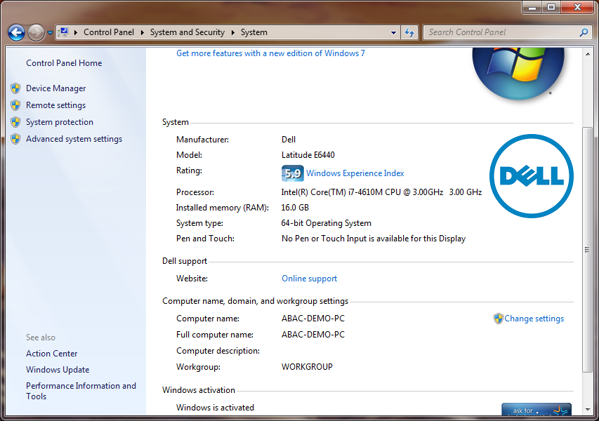
Click on Change settings.
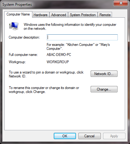
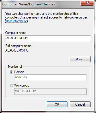
Click on the Change button.
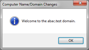
Select Domain.
Enter the domain to join, “abac.test.” It will require authentication using a user that’ is capable of adding a computer to the domain controller.
2.2.1. Configure MS Native Supplicant for Wired 802.1x
On the client PC, go to Control Panel > System and Security > Administrative Tools > Services.
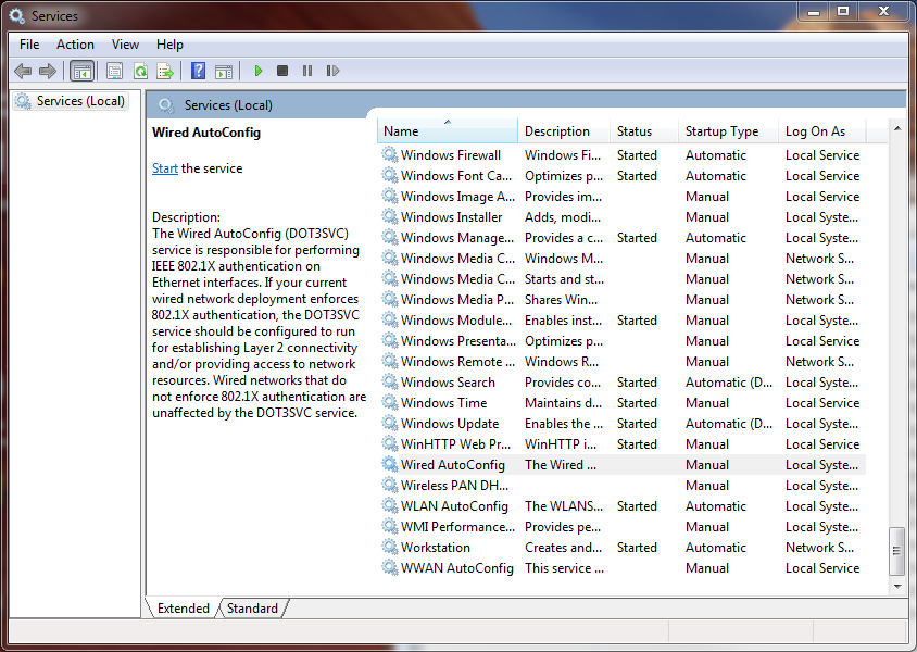
Right-click on Wired AutoConfig.
Select Properties.
Change the Startup type to Automatic.
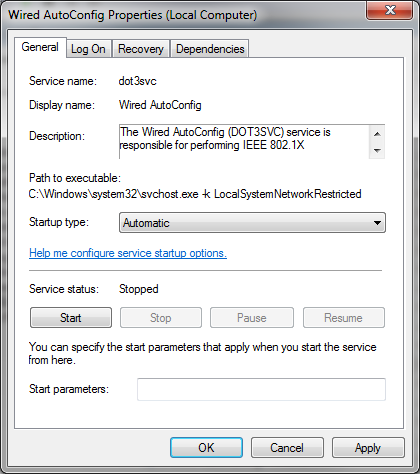
Click Apply.
Click OK.
Go to Control Panel > Network and Internet > Network and Sharing Center.
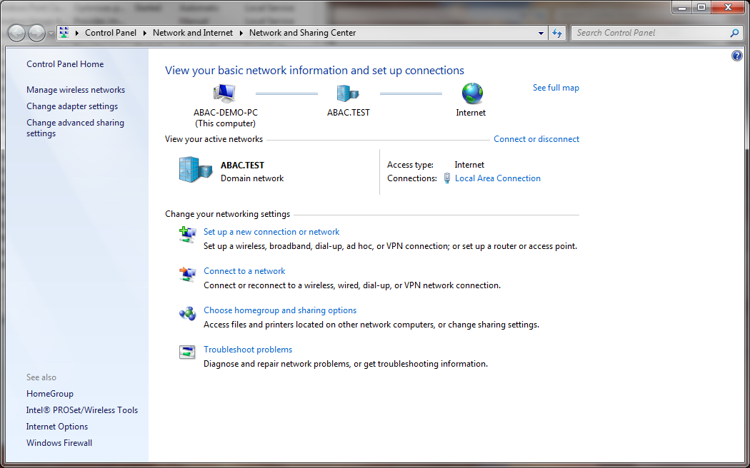
Click on Change adapter settings.
Right-click on your connection adapter and select Properties.
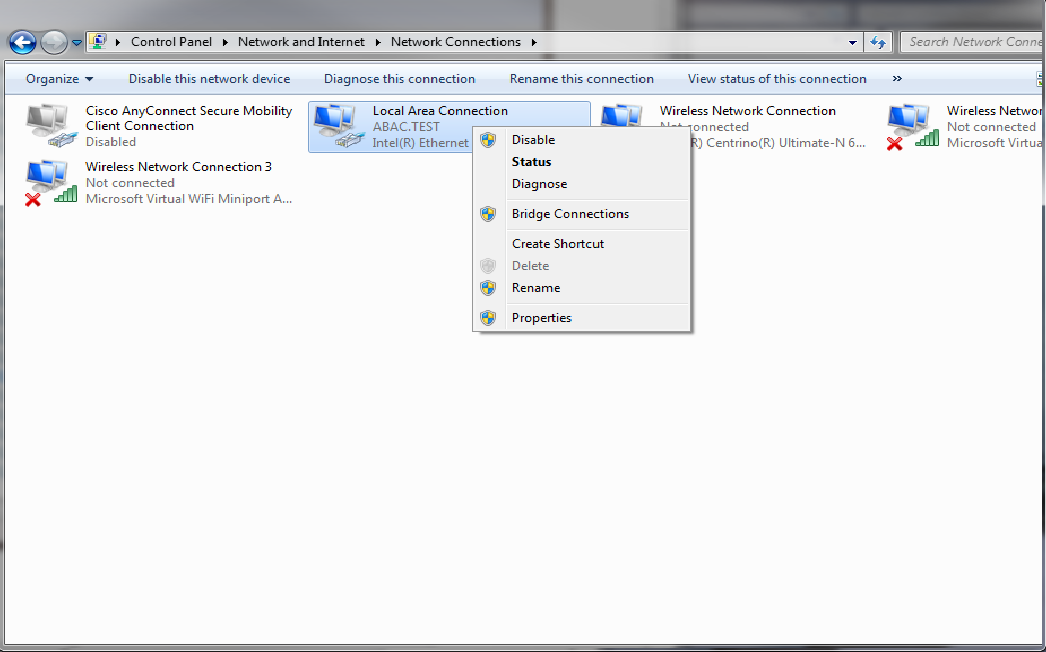
Click the Authentication tab.
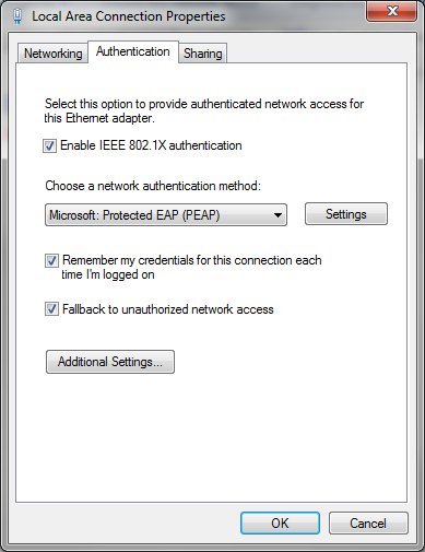
Click on Additional Settings.
Check the Specify Authentication Mode checkbox.
Select User of computer authentication.
Check the Enable single sign on for this network checkbox.
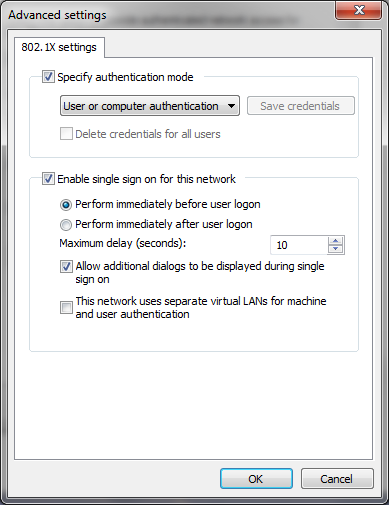
Click OK.
Click on Settings next to Microsoft: Protected EAP (PEAP).
Uncheck Validate server certificate.
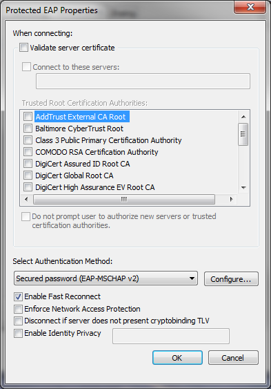
Click OK and proceed back to the desktop and log out.
2.3. Install Nginx Web Server
A web server is required for NAD redirects during the Situational Context Connector’s authentication flow. In our build, we implemented the web server using Nginx.
Log on to the server that will host the Nginx web server.
Follow the instructions at the link below to install Nginx on Windows.
2.4. Install Microsoft AD
Log on to the server that will host Microsoft AD.
Follow the instructions at the link below to create a new Microsoft AD domain that will store the accounts and identity information for the identity provider.
During setup, you will be asked to provide a name for your new domain. The name of the domain used for this build is ABAC.TEST.
2.4.1. Create a User in Microsoft AD
To create a user account in the Microsoft AD Domain:
Launch the Active Directory Users and Computers program.
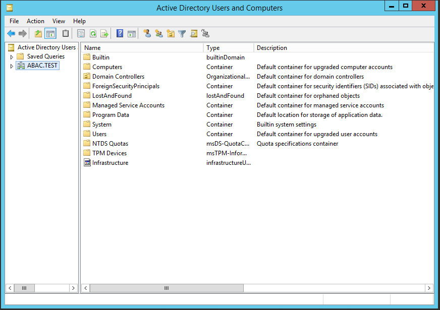
Click on the name of your domain in the left pane and then right-click on the Users folder in the right pane. In this guide, the name of the domain is “ABAC.TEST.”
In the pop-up menu that appears, select New, and then select User.
In the New Object - User screen that appears, type the First and Last name of the user, as well as their User logon name (that is, the account name).
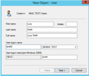
Click Next.
In the password screen that appears, type in the user’s initial password. Then, type it again in the Confirm password field. When users log in for the first time, they will be prompted to create their own unique password.
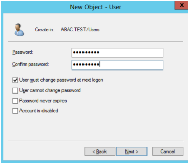
Click Next.
In the confirmation screen with information about the new user that appears, click Finish to complete the operation.
When the user logs on to the domain for the first time, the user will be prompted to create a new, unique password.
The following illustrations demonstrate what the new password screens may look like on Microsoft Windows Server 2012 when the user Lucy Smith attempts to log on to a computer in the ABAC.TEST domain using her user name lsmith and the initial password.
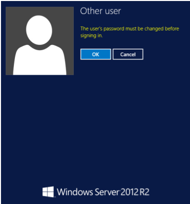
When Lucy clicks OK, she will see the screen below. She will type in her new password, which adheres to the organization’s password strength policy; then she will type the password in again to confirm.
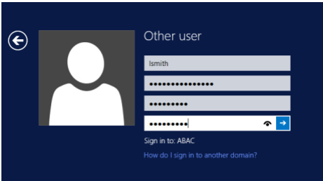
When she presses Enter, Microsoft Windows will change her password.
2.4.2. Create the Lightweight Directory Access Protocol User for Federated Authentication
Follow the steps in the previous section to create a user named Lightweight Directory Access Protocol (LDAP) user in Microsoft AD. The PingFederate-IdP will use this user account to perform LDAP queries in Microsoft AD.
2.4.3. Create the LDAP User for Cisco ISE Administration
Follow the steps in the previous section to create a user named ciscoise_svc_account in Microsoft AD. The Cisco ISE will use this user account to perform LDAP queries in Microsoft AD.
2.5. Configure the Cisco Switch
The Cisco Switch is configured in this build to represent realistic network segmentation separating users and protected network components and services on the IdP’s network. Two virtual local area networks (VLANs) are configured, and traffic is routed between the user VLAN and the services VLAN.
Complete the initial setup of the switch with the Running Express Setup instructions found in the document “Getting Started Guide for the Catalyst 2960-X and 2960-XR Switches,” available at the link below.
The switch in our build is configured as seen below.
service timestamps debug datetime msec
service timestamps log datetime msec
no service password-encryption
!
hostname Switch
!
boot-start-marker
boot-end-marker
!
!
username admin privilege 15 secret 5 $1$ZHMh$mD3FQRDvhAVbuFg49iOyq.
aaa new-model
!
!
aaa authentication login default local
aaa authentication dot1x default group radius
aaa authorization console
aaa authorization exec default local
aaa authorization network default group radius
aaa accounting update periodic 5
aaa accounting dot1x default start-stop group radius
!
!
!
!
!
aaa server radius dynamic-author
 client 10.33.7.9 server-key [xxxxxxxxxxxxxxxx]
!
aaa session-id common
clock timezone EST -4 0
switch 1 provision ws-c2960x-24ts-l
!
!
!
!
ip dhcp excluded-address 10.33.50.193 10.33.50.194
ip dhcp excluded-address 10.33.7.1 10.33.7.230
!
ip dhcp pool CLIENTS
 network 10.33.50.192 255.255.255.240
 default-router 10.33.50.193
 dns-server 10.97.74.8
!
ip dhcp pool NCCOE
 network 10.33.7.0 255.255.255.0
 default-router 10.33.7.1
 dns-server 10.97.74.8
!
!
ip domain-name abac.test
ip name-server 10.33.7.230
vtp mode transparent
!
!
!
!
!
epm logging
!
!
crypto pki trustpoint TP-self-signed-1455706752
 enrollment selfsigned
 subject-name cn=IOS-Self-Signed-Certificate-1455706752
 revocation-check none
 rsakeypair TP-self-signed-1455706752
!
!
crypto pki certificate chain TP-self-signed-1455706752
 certificate self-signed 01
 3082022B 30820194 A0030201 02020101 300D0609 2A864886 F70D0101 05050030
 31312F30 2D060355 04031326 494F532D 53656C66 2D536967 6E65642D 43657274
 69666963 6174652D 31343535 37303637 3532301E 170D3136 30383135 32313530
 35385A17 0D323030 31303130 30303030 305A3031 312F302D 06035504 03132649
 4F532D53 656C662D 5369676E 65642D43 65727469 66696361 74652D31 34353537
 30363735 3230819F 300D0609 2A864886 F70D0101 01050003 818D0030 81890281
 8100970B 2180DACE EC47660F 5DCEEBC8 8E55475C 39A36018 FE770EFF 378662F6
 8846AD8E D4F0E922 33E1B06E AA2526F0 16A8B451 07227347 2B82C6F6 EFA04BAC
 D561EBA9 F0B85AE2 C50977DC 605D7573 489FD27B 0583F6FE 8D70DF0B CBD3162B
 9E1FE937 371FA4AE 905EA47A 667ACC32 05D5DC7F 1E582001 DD40C159 3A21479C
 D34F0203 010001A3 53305130 0F060355 1D130101 FF040530 030101FF 301F0603
 551D2304 18301680 1457B47B 85B93B03 3557754B 9298D87C 89EED062 64301D06
 03551D0E 04160414 57B47B85 B93B0335 57754B92 98D87C89 EED06264 300D0609
 2A864886 F70D0101 05050003 81810079 9AE74655 14C450FE 6F6B4E63 1CBCD9AF
 15D8B911 2C55785A 020E18C7 4F3C28A7 A714E961 933DE0DF F3FB19F6 08AA2FD4
 DCD95B9F 161317C0 3BDCD75F D4850E06 38153D02 260300D1 8D1D8794 9B9A0A3B
 C69269C6 E83CD422 F24F3C17 1AE8F70A F75E7B0F A8FF7946 85328DFB 1C39F676
 C3FC5B29 A1900D37 E7226576 183765
        quit
dot1x system-auth-control
!
spanning-tree mode rapid-pvst
spanning-tree extend system-id
!
!
!
!
vlan internal allocation policy ascending
!
vlan 207,2084
!
!
!
!
!
!
!
!
!
!
!
!
interface FastEthernet0
 no ip address
 no ip route-cache
!
interface GigabitEthernet1/0/1
 switchport access vlan 207
 spanning-tree portfast edge
!
interface GigabitEthernet1/0/2
 switchport access vlan 2084
 switchport mode access
 spanning-tree portfast edge
!
interface GigabitEthernet1/0/3
 switchport access vlan 207
 spanning-tree portfast edge
!
interface GigabitEthernet1/0/13
 switchport access vlan 2084
 spanning-tree portfast edge
!
interface GigabitEthernet1/0/20
 switchport access vlan 2084
 switchport mode access
 authentication event fail action next-method
 authentication order dot1x mab
 authentication priority dot1x mab
 authentication port-control auto
 authentication violation restrict
 snmp trap mac-notification change added
 snmp trap mac-notification change removed
 dot1x pae authenticator
 dot1x timeout tx-period 10
 spanning-tree portfast edge
 spanning-tree bpduguard enable
!
interface GigabitEthernet1/0/21
 switchport access vlan 207
 switchport mode access
 authentication event fail action next-method
 authentication order dot1x mab
 authentication priority dot1x mab
 authentication port-control auto
 authentication violation restrict
 snmp trap mac-notification change added
 snmp trap mac-notification change removed
 dot1x pae authenticator
 dot1x timeout tx-period 10
 spanning-tree portfast edge
 spanning-tree bpduguard enable
!
interface Vlan1
 no ip address
 no ip route-cache
!
interface Vlan207
 ip address 10.33.7.2 255.255.255.0
!
interface Vlan2084
 ip address 10.33.50.194 255.255.255.240
 ip helper-address 10.33.7.9
!
ip default-gateway 10.33.7.1
ip http server
ip http authentication local
ip http secure-server
!
!
ip access-list extended ACL-REDIRECT
 deny ip any host 10.33.7.9
 permit ip any host 10.33.7.6
ip radius source-interface Vlan207
logging origin-id ip
logging source-interface Vlan207
logging host 10.33.7.9 transport udp port 20514
access-list 10 permit 10.33.7.9
access-list 10 deny any log
!
snmp-server community ciscoro RO 10
snmp-server trap-source Vlan207
snmp-server source-interface informs Vlan207
snmp-server enable traps snmp linkdown linkup
snmp-server enable traps mac-notification change move threshold
snmp-server host 10.33.7.9 version 2c cisco mac-notification
!
radius-server attribute 6 on-for-login-auth
radius-server attribute 8 include-in-access-req
radius-server attribute 25 access-request include
radius-server dead-criteria time 30 tries 5
!
radius server ABAC-CiscoISE
 address ipv4 10.33.7.9 auth-port 1812 acct-port 1813
 key [xxxxxxxxxxxxxxxx]
!
!
line con 0
line vty 0 4
 exec-timeout 300 0
 logging synchronous
line vty 5 15
 logging synchronous
!
ntp server 10.97.74.8
mac address-table notification change
mac address-table notification mac-move
!
end
2.6. Install and Configure Cisco Identity Services Engine
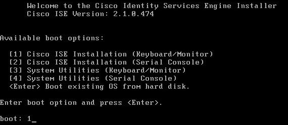
On a Redhat or CentOS server, boot from the Cisco ISE iso file.
At the installation screen, choose your boot option and press Enter.
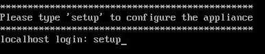
Once installation is complete, it restarts. Enter setup and press Enter.
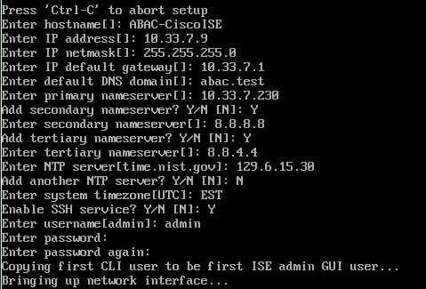
Enter ISE configuration information (ISE hostname, Internet Protocol [IP] addresses, domain name service [DNS] domain and name servers, Network Time Protocol [NTP] server, time zone, username, and password):
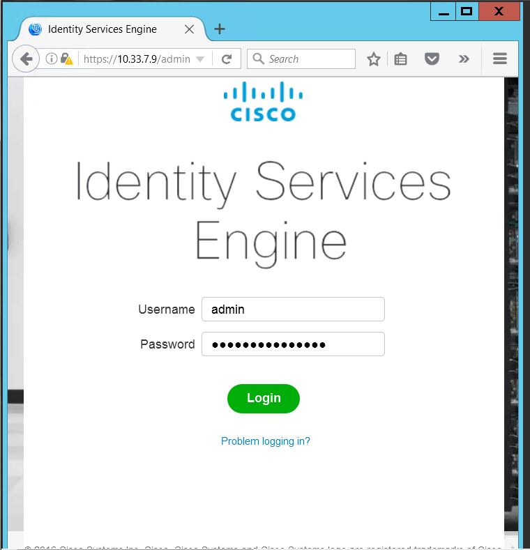
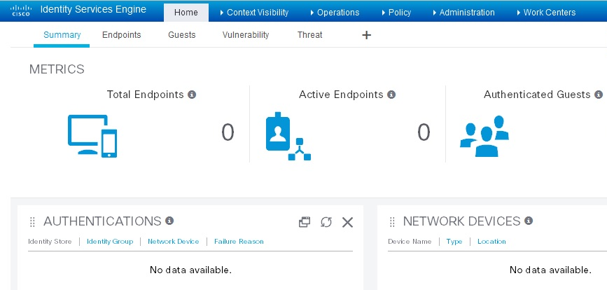
ISE will continue and create the database. ISE will automatically reboot after a successful installation. After the reboot, you can log in to ISE via any browser reachable in your domain by entering https://<IP Address of ISE server>/admin, as seen below:
After logging in, you will see the default ISE dashboard:
2.6.1. Configure Cisco ISE with Microsoft AD
While logged in to the ISE administration console, navigate to Administration > Identity Management > External Identity Sources > Active Directory.
Follow the instructions at the link below, beginning on page 11, Steps 1-9, to configure Cisco ISE with Microsoft AD. Note: these instructions are in the section Testing Environment > Cisco Identity Service Engine (ISE 2.0) VM Setup > Initial ISE Setup > AD User Setup.
Note: At step 3, provide the credentials of the user account created earlier to join ISE to the existing AD domain (eg, ciscoise_svc_account).
2.6.2. Add Network Device to ISE
Follow the instructions at the link below, beginning on page 14, Steps 1-3, to register the NAD with ISE. Note: these instructions are in the section Testing Environment > Cisco Identity Service Engine (ISE 2.0) VM Setup > Initial ISE Setup > Network Devices.
Note: The shared secret used on Step 2, “Enable Radius Authentication Settings and enter the shared secrets,” must be the same key that was used for configuring aaa on the switch. If the switch has not yet been configured, remember to record the secret used here so that it can be used when configuring aaa on the switch.
2.6.3. Configure ISE for pxGrid
Follow the instructions at the link below, beginning on page 15, Steps 1-4, to enable a pxGrid persona, used by the Situational Context Connector to query ISE for device and network attributes. Note: these instructions are in the section Configuring ISE for pxGrid.
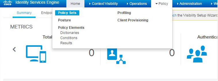
2.6.4. Enable ISE Policy Sets
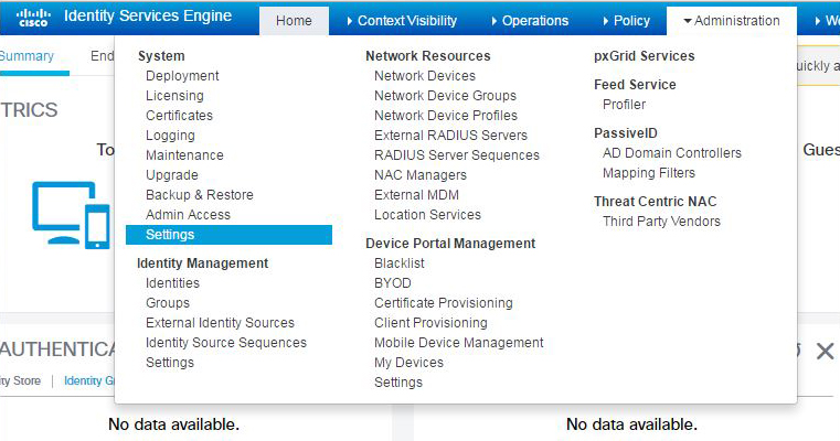
Navigate to Administration > System > Settings.
In the left sidebar, click on Policy Sets.
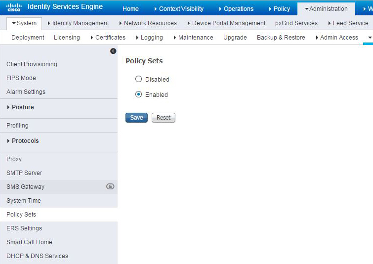
Click the Enabled radio button.
Click Save.
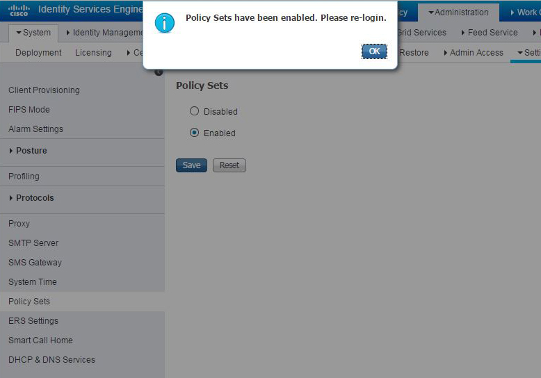
In the pop-up, click OK and log back into ISE.
2.6.5. Configure Authentication Policy
Navigate to Policy > Policy Sets.
In the left sidebar, click on Default.
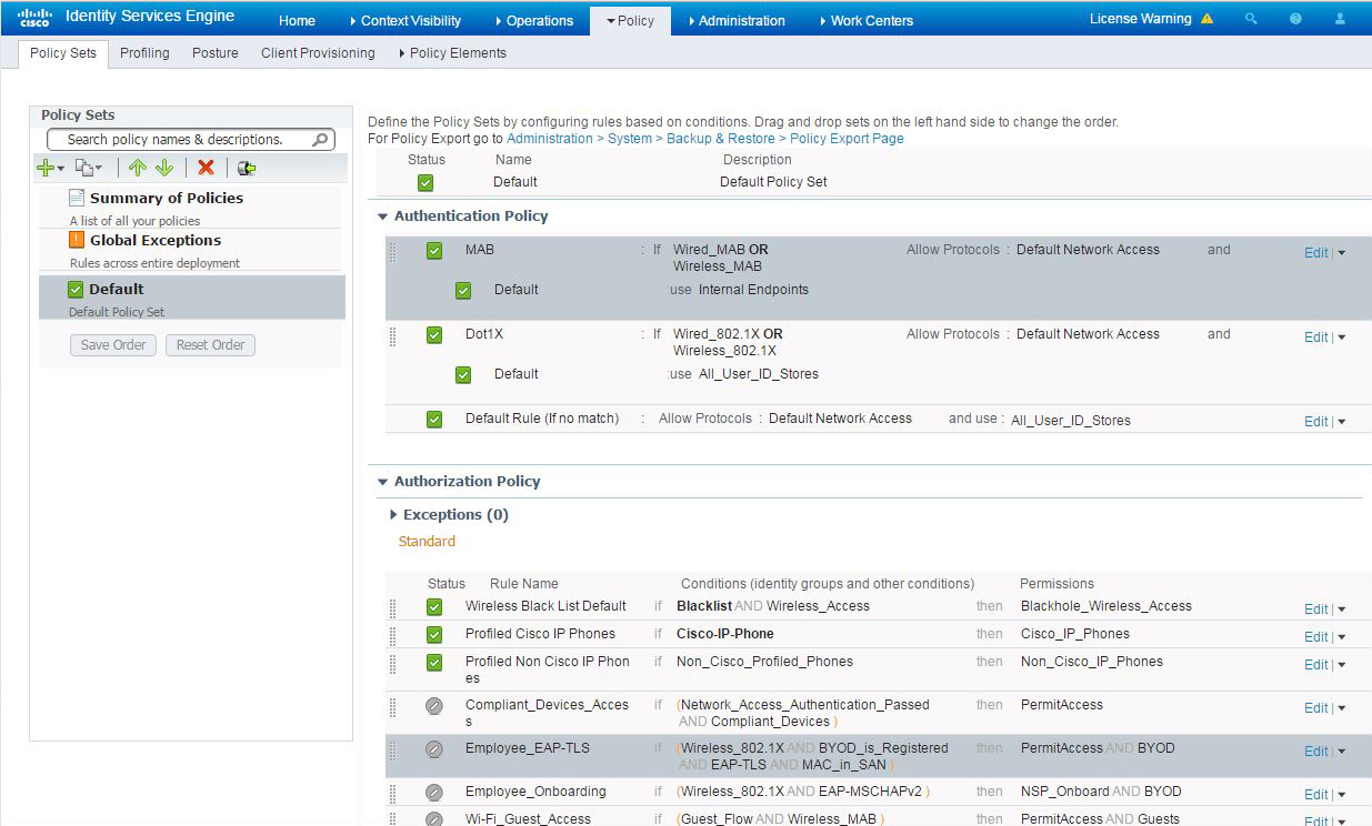
Click on the Dot1x rule.
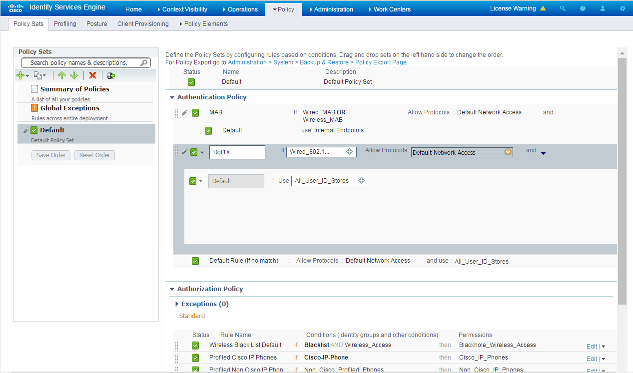
Click on the plus icon.

Change the value of Identity Source to “pxGrid_Users.”
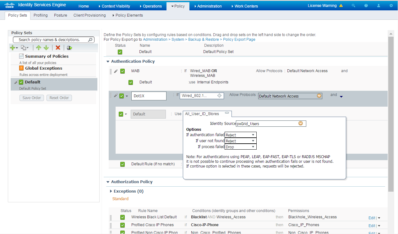
Scroll to the bottom of the page and click Save.
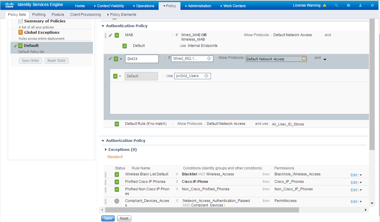
2.6.6. Configure Authorization Policy
Navigate to Administration > Guest Access.
In the sidebar, click on Guest Portals.
Click Create.
Choose Sponsored Guest Portal.
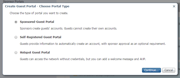
Click Continue.
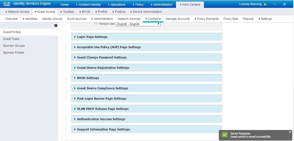
Provide a name, ABAC-Guest.
Under Portal settings, set the HTTPS port to 8000.
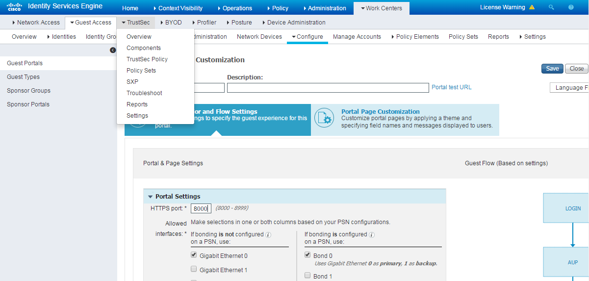
Click Save.
In the main menu, navigate to Policy > Policy Elements.
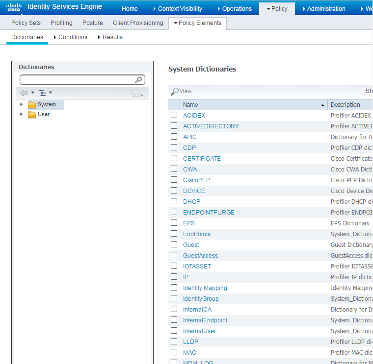
In the submenu, navigate to Results > Authorization > Authorization Profiles.
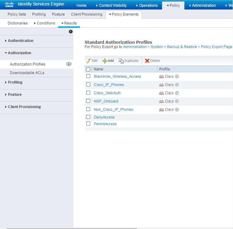
Click Add.
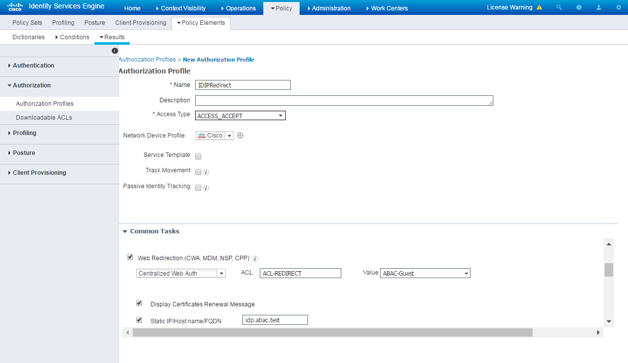
In the name field, enter “IDIPRedirect.”
Set the access type to “ACCESS_ACCEPT.”
Under Common Tasks, put a check next to Web Redirection (CWA, MDM, NSP, CPP).
In the revealed fields, choose Centralized Web Auth.
Set the ACL field to “ACL-REDIRECT.”
Set the value such that it matches the created guest portal, “ABAC-Guest.”
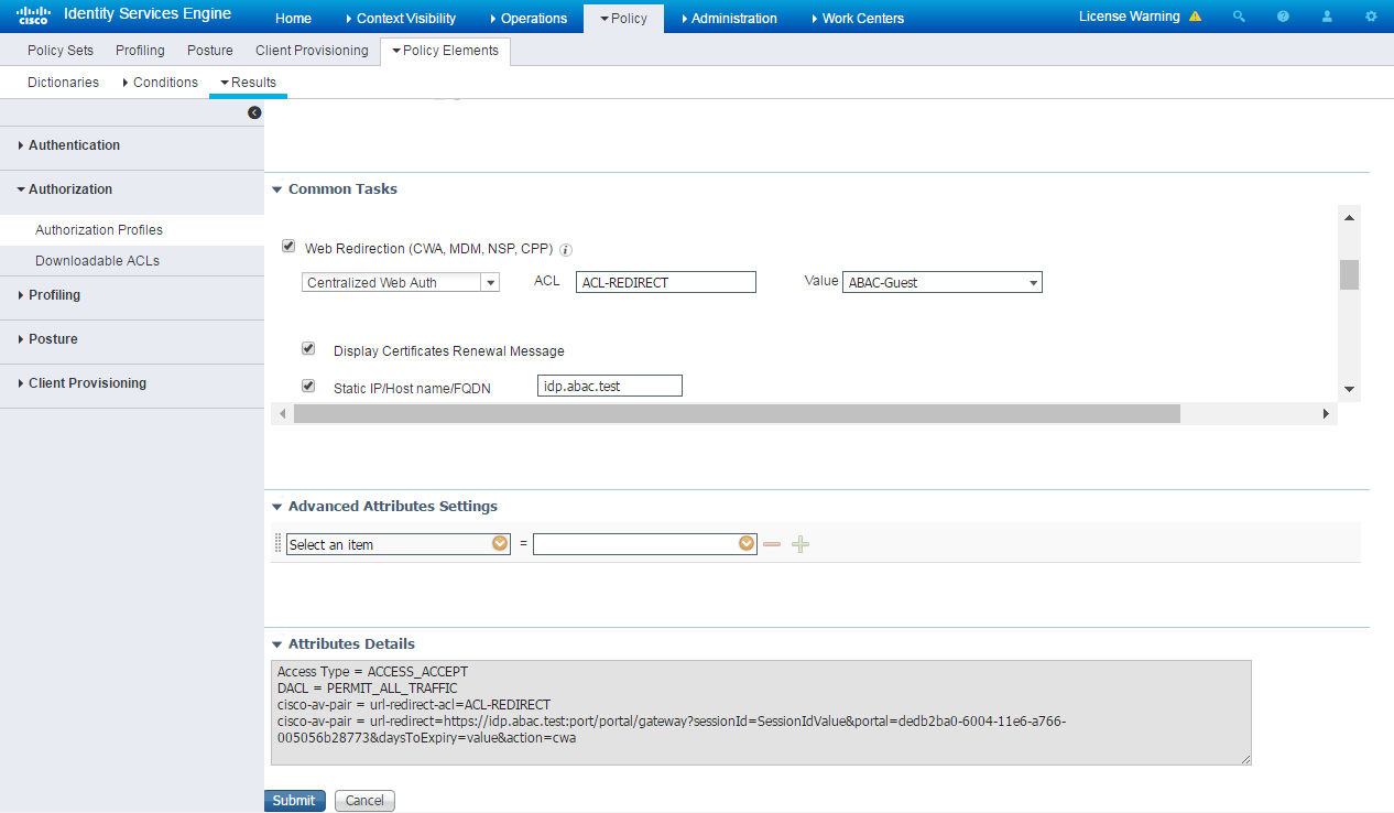
Put a check next to Static IP/Host name/FQDN.
Enter the hostname of the server on which Ping Federate is running, “idp.abac.test.”
Click Submit.
2.6.7. Add Rule for Authorization Policy
Navigate to Policy > Policy Sets.
In the right sidebar, click on Default.
Under the Authorization Policy section, click the triangle next to edit.
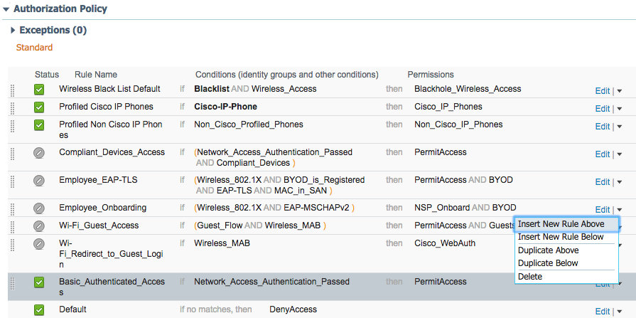
Provide a name for the rule, IDIP REDIRECT.
Click the plus button next to condition.
Choose, Select Existing Condition from Library.
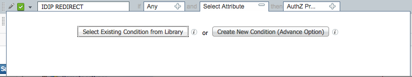
Click the arrow next to Select Condition
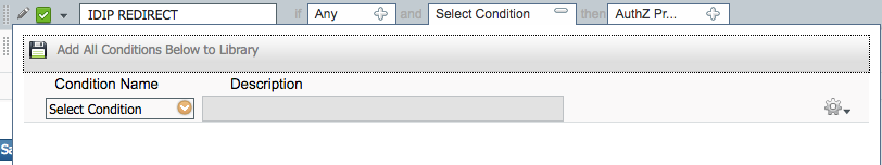
Choose Compound Conditions.

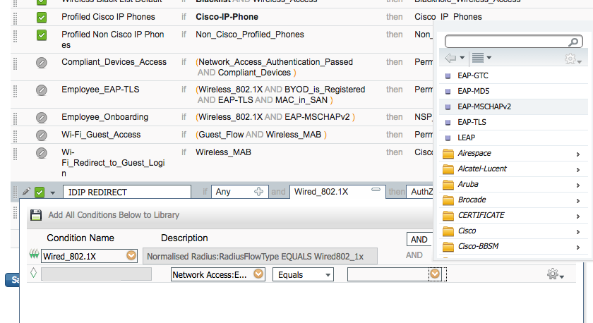
Choose wired_802.1x.

Click the cog icon.
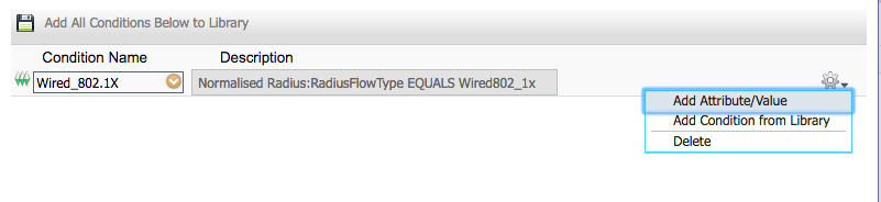
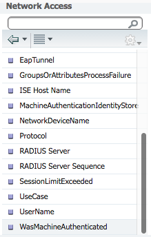
Choose Add Attribute/Value.
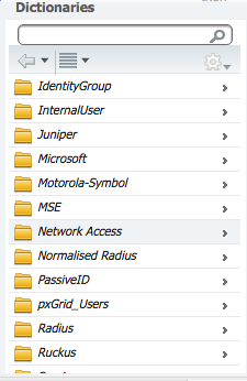
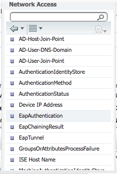
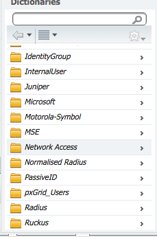
Select Network Access.
Select EapAuthentication.
Click the arrow in the box next to Equals.
Select EAP-MSCHAPv2.
Click the plus icon in the then box.
Select Standard.

Select IDIPRedirect.

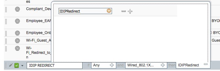
Click Done.

Click Save.

Machine Authorization Policy Rule
- Navigate to Policy > Policy Elements > Results.
- In the left sidebar, navigate to Authorization > Downloadable ACLs.
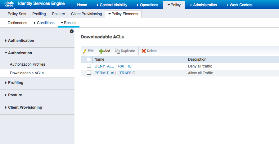
Click Add.
For Name enter Wired_AD_ONLY.
For DACL Content match the entry below.
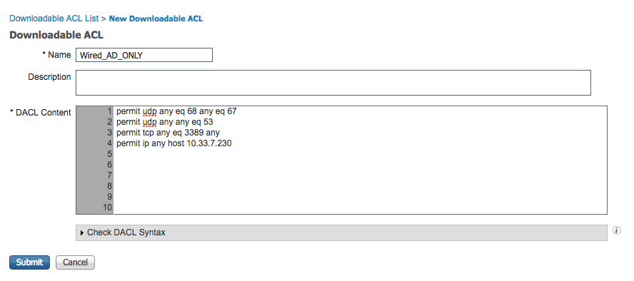
Click Submit.
Navigate back to Policy > Policy Sets.
Click on Default in the left sidebar.
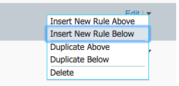
Click the triangle next to the edit button on the IDIP REDIRECT line.
Click Insert New Rule Above.

Enter Wired Machine for the name.
Click the plus button next to condition.
Choose Create New Condition.
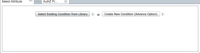
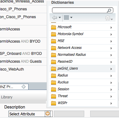
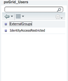
In the Select Attribute box, click the arrow.
Select PxGrid_Users.
Select ExternalGroups.
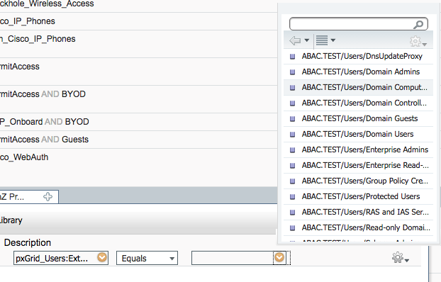
In the equals box, click the arrow.
Select ABAC.TEST/Users/Domain Computers.
In the Then box, click on the plus icon.
Click the arrow in the Select an Item box.
Click the cog in the top right of the pop-up window.
Select Add New Standard Profile.

Name the profile Wired_AD_ONLY.
In the Common Tasks section, check the box next to DACL Name.
Select Wired_AD_ONLY from the drop-down.
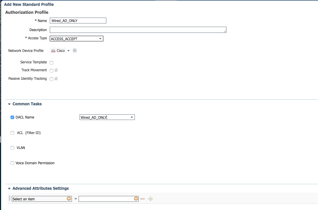
Click Save.
The completed rule should look similar to the one below.

User Authorization Policy Rule
Navigate back to Policy > Policy Elements > Results.
In the left sidebar, click on Authorization > Downloadable ACLs.
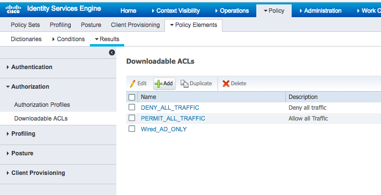
Click Add.
In the Name field, type Wired_PERMIT_ALL.
In the DACL Content field, type permit ip any any.

Click Submit.
Navigate back to Policy > Policy Sets.
Click on Default in the left sidebar.
Click the triangle next to the edit button on the IDIP REDIRECT line.
Click Insert New Rule Below.
In the name field, type Wired User.
Click the plus icon in the condition box.
Select Create New Condition.
In the Select Attribute box, click the arrow.
Select PxGrid_Users.
Select ExternalGroups.
In the equals box, click the arrow.
Select ABAC.TEST/USERS/Domain Users.

Click the cog.
Select Add Attribute/Value.
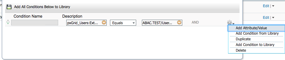
In the new attribute box, select Network Access.
Select WasMachineAuthenticated.
In the equals box, select True.
In the then box, click the plus icon.
Click Select an item.
Click the cog.
Select Add New Standard Profile
In the name field, put Wired_PERMIT_ALL.
In the Common Tasks section, check the box next to DACL Name.
In the box that appears, select Wired_PERMIT_ALL.
Click Save.
Back on the Policy page, click Save again. The final rule should
look similar to the one below.

2.7. Install RSA AA
RSA AA (On-Premise) comes packaged as a virtual snapshot that must be installed on a virtual machine (VM). A full installation requires core and back office applications, database scripts, and maintenance tools – all necessary for this build. Follow these instructions to install RSA AA for the identity provider.
Log on to VMware and load the RSA AA virtual appliance (e.g., Adaptive Authentication [On-Premise] 7.0.0.0-SNAPSHOT).
Start the RSA AA VM using VMware.
Log on to the server that hosts the new VM.
Launch the RSA AA installation file.
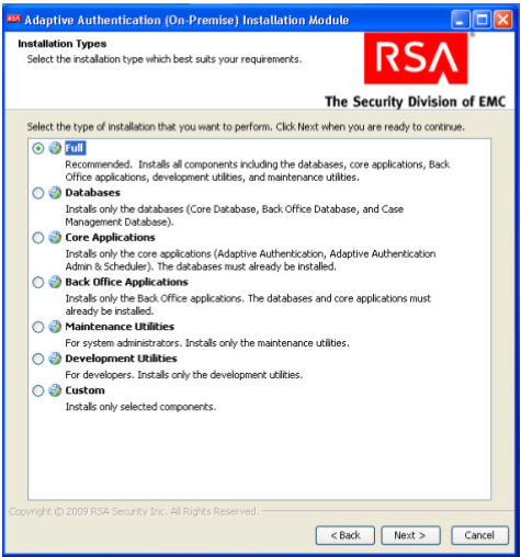
On the Installation Types screen, select Full to install all required components. Then, click Next.
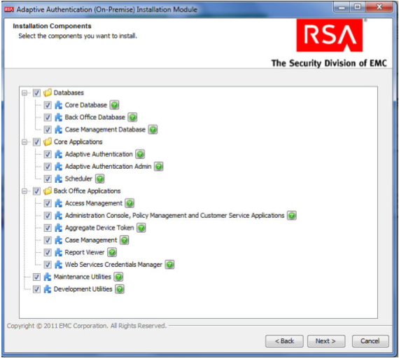
Click Next in the Installation Components screen.
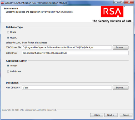
In the environment screen, set the database type (MS SQL) and the JDBC driver file as shown in the following screenshot.
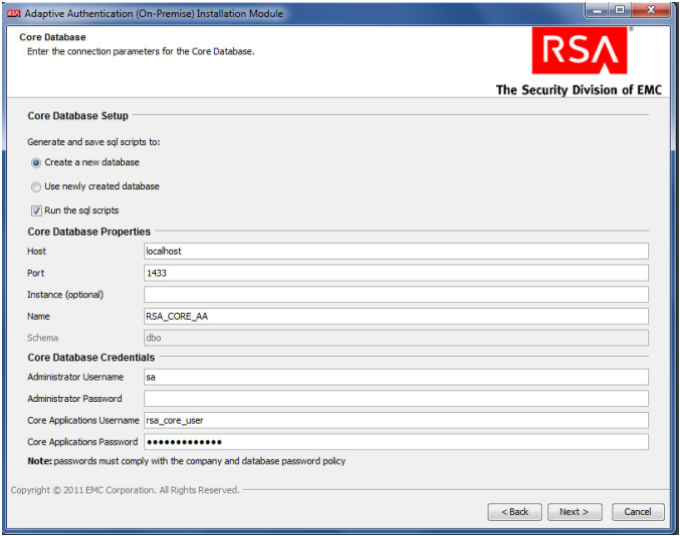
For the core database setup, create a new database, and set the core database properties and credentials.
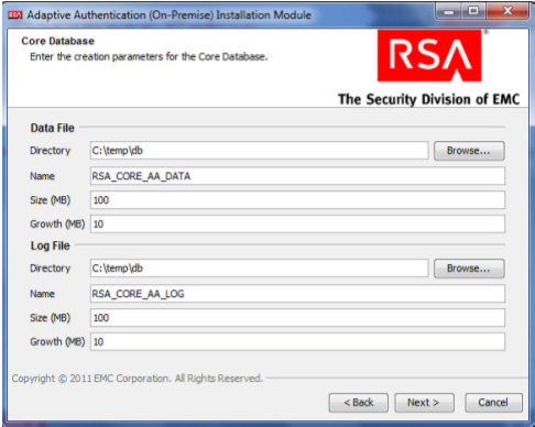
On the Core Database screen, set parameters for the data and log files (directory, name, size, and growth).
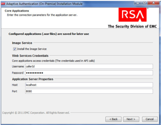
On the Core Applications screen, select to install the image service, and provide the web service credentials and application server properties.
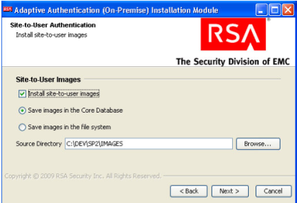
On the Site-to-User Authentication screen, select Install site-to-user images, which defines how the site authenticates users. Select Save images in the Core Database and select the directory shown in the following screenshot as the source directory. During enrollment, users are asked to select a personal image for authentication.
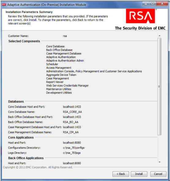
Review the configuration options on the Installation Parameters Summary and click Install. Once complete, you can confirm that the installation was successful by viewing the log files.
2.8. Configure RSA AA Rules
RSA has a built-in policy management application that allows administrators to create and update rules for user login based on various scenarios. For example, high-risk users can be required to answer challenge questions or respond to an out-of-band SMS. For more information, see the Back Office User’s Guide. This example shows how to create a challenge rule for users to confirm identity for large transactions using an out-of-band SMS code. RSA Back Office allows administrators to manage setup policy for enabling the enhanced features provided by the RSA adapter, such as answering challenge questions and providing SMS confirmation codes enabled through this interface.
2.8.1. Create Rule for Non-Persistent User Enrollment
RSA AA requires information for each user to help verify their identity. These users are classified into two groups: persistent and non-persistent users. A rule is created to request enrollment information for non-persistent users, those not kept in the user database.
Log in to the Back Office application [http://xxx.xxx.xxx.xxx:8080/backoffice]
Once logged in, click Manage Rules under Policy Management. Select New Rule.
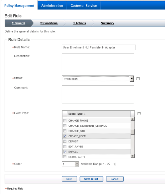
In the Rule Details (in the General tab):
Set Rule Name to User Enrollment Not Persistent - Adapter.
Set the Status to Production.
Note: The rule cannot be in production until it is created and approved by an administrator.
In Event Type, select Create User and Enroll.
Set the Order to 1.
Click Next.
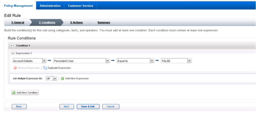
In the Rule Conditions page, add a condition (Condition 1) and with one expression (Expression 1). Set Expression 1 to Account Details such that Persistent User is Equal to FALSE.
Click Next.
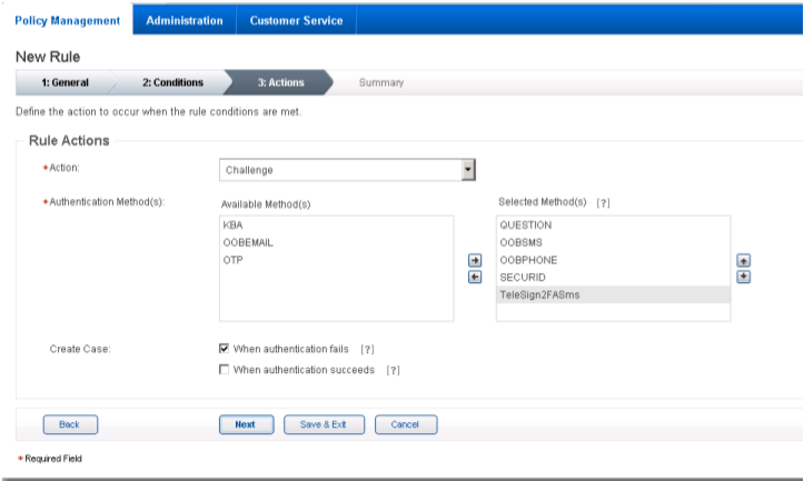
In the Rule Actions page:
- Set Action to Challenge.
- Set Authentication Methods to QUESTION, OOBSMS, OOBPHONE, SECURID, and TeleSign2FASms.
- In Create Case, make sure that only for when authentication fails is selected. Then, click Next.
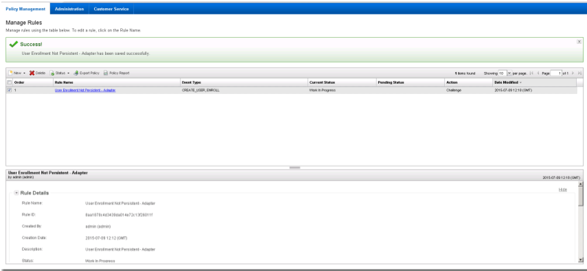
Review the rule settings in the Summary page. Then, click Save and Finish.
Once created, a rule is in Work in Progress status until approved by an administrator.
Click Status and Approve Status, then click Approve to set rule to Production status.
You can use these steps to create each of the rules in the following sections.
2.8.2. Create Rule for Persistent User Enrollment
Persistent users are those that will be added to the user table.
Table 2‑1 Persistent User Enrollment
| Rule Name | User Enrollment Persistent –Adapter |
|---|---|
| Event Type | Create User, Enroll |
| Rule Order | 2 |
| Rule Condition | IF (Account Details > Persistent User Equal to TRUE) |
| Rule Action | Allow |
| Authentication Method | |
| Create Case | No |
2.8.3. Create Rule for User Updates
Once users are created, a rule is applied to allow persistent users to update their information.
Table 2‑2 User Update
| Rule Name | User Update |
|---|---|
| Event Type | User Update |
| Rule Order | 3 |
| Rule Condition | IF (Account Details > Persistent User Equal to TRUE) |
| Rule Action | Allow |
| Authentication Method | |
| Create Case | No |
2.8.4. Create Rule for Challenge SMS
In this build, large transactions require users to respond to an out-of-band SMS challenge during authentication. When transactions meet the prerequisite, a random code will be sent to the user’s SMS-enabled device that must be entered to confirm the transaction.
Table 2‑3 Out-of-Band SMS
| Rule Name | Challenge SMS for Payment |
|---|---|
| Event Type | Challenge |
| Rule Order | 4 |
| Rule Condition | IF (Transaction Details > Transaction Amount is BETWEEN 5000 and 10000) |
| Rule Action | Allow |
| Authentication Method |
|
| Create Case | When Authentication Succeeds |
2.8.5. Increase SMS Token Length
The default token length for out-of-band SMS is currently set to four digits. Access the Administration tab on the Back Office application. Under Components, select Authentication Methods and scroll down to the Out-of-Band SMS section. Adjust the token length by changing the value of SMS - OTP Token Length to six.
Figure 2‑1 Out-of-Band Token Length

2.8.6. Create Policy for Session Sign-In
The following rules create different sign-in scenarios for users based on an RSA-generated risk score at the time of login. RSA AA uses a risk engine to give users a risk score to determine a level of trust at the time of access. See the tables in Section 2.8.8 for the session sign-in parameters for each risk level. Before the session sign-in rules are created, lists need to be created to group users together. This build will group users into four categories based on risk level (low, medium, high, and critical).
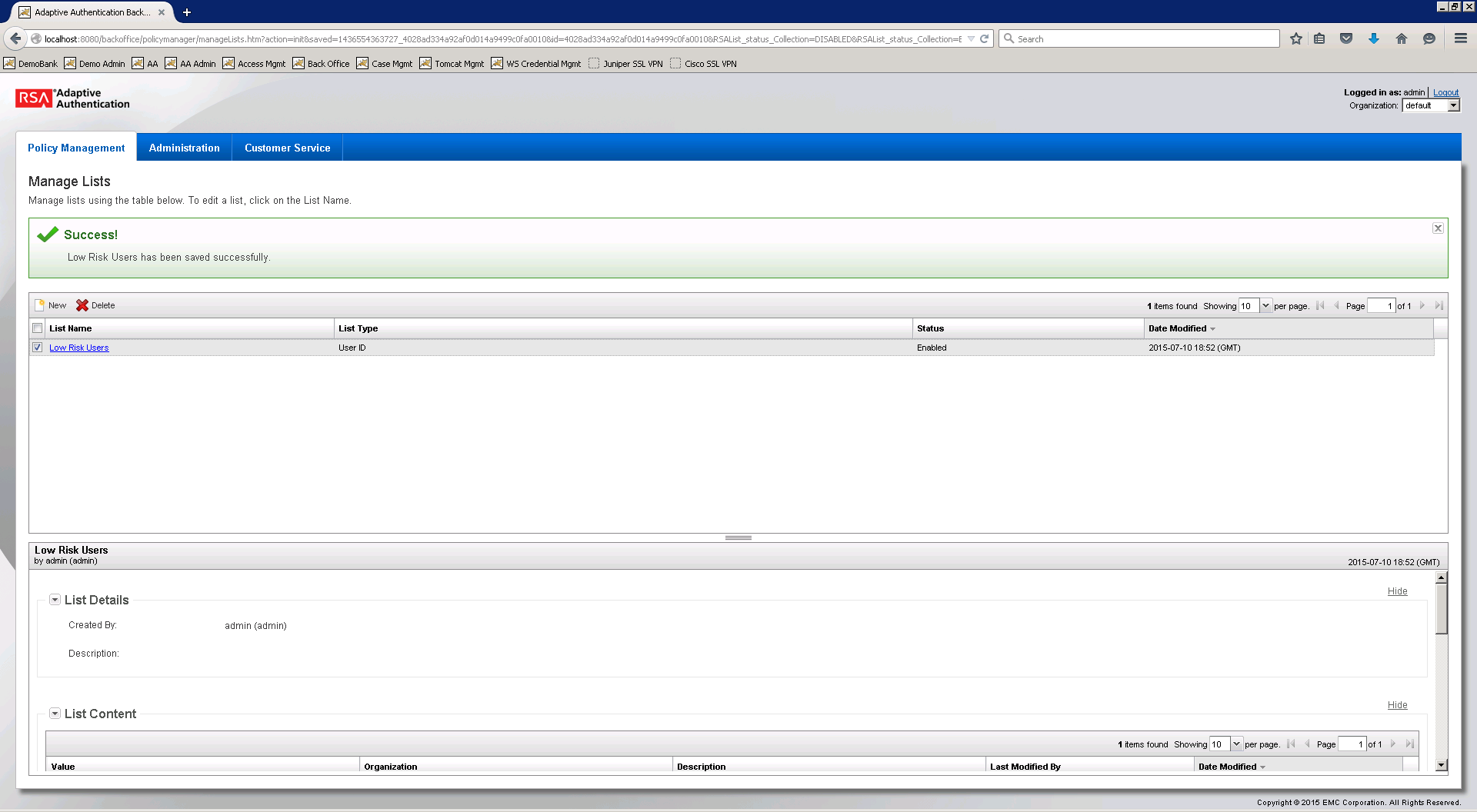
2.8.7. Create Lists for Session Sign-In
- Log in to the Back Office application.
- Go to Policy Management and select Manage Lists.
- Set List Name to Low Risk Users, List Type to User ID, and Status to Enabled.
- Under List Content, select Add Value and set the Value to demolowrisk and Organization to default.
- Click Add Value.
- Click Save.
Repeat these steps to create a list for Medium, High, and Critical risk users.
Figure 2‑2 Successful List Created
2.8.8. Create Rules for Session Sign-In
Repeat the steps as in Section 2.8.1 to create the session sign-in rules for different user groups.
Table 2‑4 Session Sign-In – Low Risk
| Rule Name | Session Sign In – Low Risk |
|---|---|
| Event Type | Session Sign-in |
| Rule Order | 5 |
| Rule Condition | IF (Account Details > User ID within Low Risk Users) |
| Rule Action | Allow |
| Authentication Method | |
| Create Case | No |
Table 2‑5 Session Sign-In – Medium Risk
| Rule Name | Session Sign In – Medium Risk |
|---|---|
| Event Type | Session Sign-in |
| Rule Order | 6 |
| Rule Condition | IF (Account Details > User ID Within Medium Risk Users) |
| Rule Action | Allow |
| Authentication Method |
|
| Create Case | When Authentication Fails |
Table 2‑6 Session Sign-In – High Risk
| Rule Name | Session Sign In – High Risk |
|---|---|
| Event Type | Session Sign-in |
| Rule Order | 7 |
| Rule Condition | IF (Account Details > User ID Within High Risk Users) |
| Rule Action | Challenge |
| Authentication Method |
|
| Create Case | When Authentication Fails |
Table 2‑7 Session Sign-In – Critical Risk
| Rule Name | Session Sign In – Critical Risk |
|---|---|
| Event Type | Session Sign-in |
| Rule Order | 8 |
| Rule Condition | IF (Account Details > User ID Within Critical Risk Users) |
| Rule Action | Challenge |
| Authentication Method |
|
| Create Case | When Authentication Fails |
2.8.9. Create Rule to Allow Forced Sign-In for Payment
The rules for session sign-in in the preceding sections were based predefined facts built within RSA AA. This build requires a rule that uses additional facts that are not within the build. Fortunately, new facts can be created within the Back Office application. Once custom facts are created, they can be used to build further rules.
2.8.10. Create Custom Fact
Log in to the Back Office application.
Go to Policy Management and select Manage Custom Facts.
Select New and set the Field Name to Force Workflow, Field Type to String, and Status to Enabled.
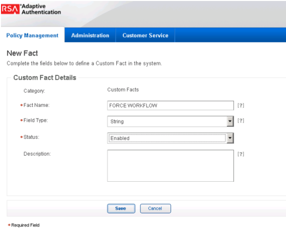
Click Save.

Create a new rule using this custom fact that allows payment if this fact is met. Use the settings in the following table.
Table 2‑8 Force Allow
| Rule Name | Force Allow |
|---|---|
| Event Type | Payment, Session Sign-in |
| Rule Order | 9 |
| Rule Condition | IF (Custom Fact > Force Workflow Equal to Allow) |
| Rule Action | Allow |
| Authentication Method | |
| Create Case | No |
2.9. Install and Configure PingFederate-RP
The PingFederate installation in this section is for the Federation Server at the RP. This is the only component at the RP in this section. Even though the goal of this section is to set up the federation for the IdP, the basic configuration of the PingFederate-RP in this section is necessary to produce metadata that is exchanged with the IdP. A complete configuration of the PingFederate-RP will be performed in Section 3 of this guide.
Log on to the RP’s server that will host the PingFederate service, and follow the instructions at the link below to install PingFederate and run it as a Windows service.
Follow these steps to perform a basic configuration of the PingFederate-RP and export the metadata.
Launch your browser and navigate to the PingFederate app URL: https://<DNS_NAME>:9999/pingfederate/app. Replace DNS_NAME with the fully qualified name of the RP’s PingFederate server (e.g., https://rp.abac.test:9999/pingfederate/app).
Log on to the PingFederate application using the credentials you configured in the previous installation section.
On the Main Menu under System Settings, click Server Settings.
Click the Roles and Protocols tab.
Select Enable Identity Provider (IdP) role and support the following.
Select SAML 2.0.
Select WS-Federation.
Select Enable Service Provider (SP) role and support the following.
Select the SAML 2.0.
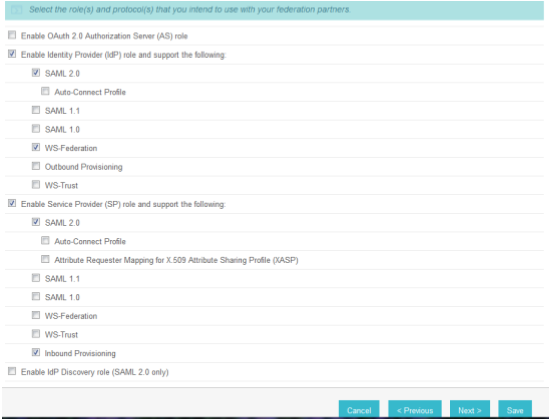
Click Next.
On the Federation Info screen, enter the Base URL and SAML 2.0 Entity ID using the format https://<DNS_NAME>:9031 (e.g., https://rp.abac.test:9031).
Enter the WS-Federation Realm using the format urn:<DNS_NAME> (e.g., urn:rp.abac.test).
Note: Keep a copy of the urn, because it will be used later to configure the WS-Federation relationship with SharePoint.
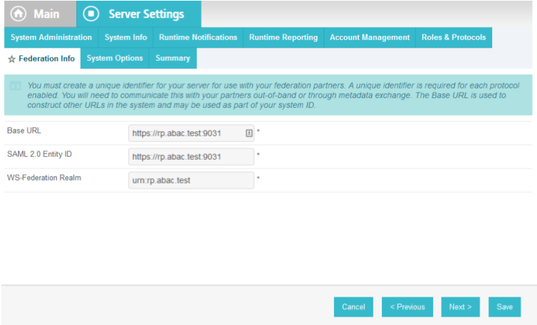
Click Save.
On the Main Menu under Administrative Functions, click Metadata Export.
On the Metadata Role screen, select I am the Service Provider (SP).
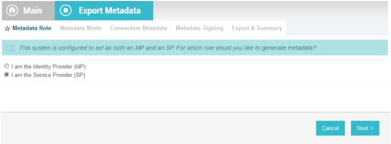
Click Next.
On the Metadata Mode screen, select Select information to include in metadata manually.
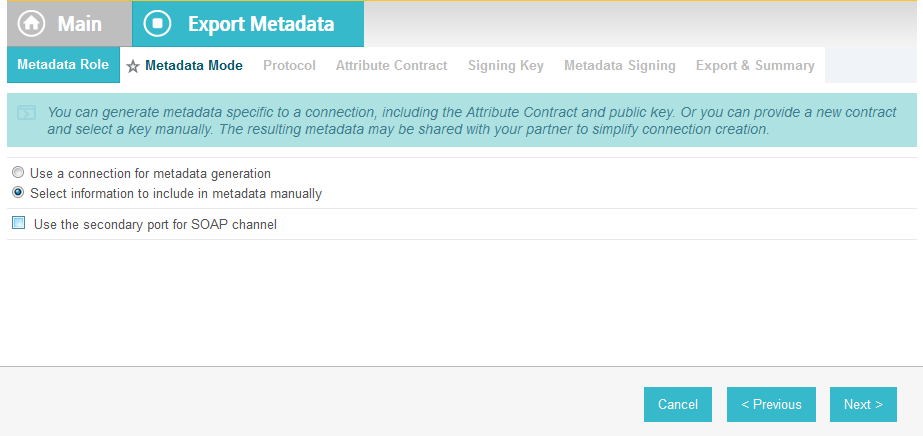
Click Next.
On the Protocol screen, make sure that SAML 2.0 is listed.
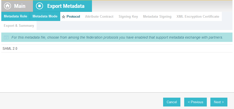
Click Next.
On the Attribute Contract screen, click Next.
On the Signing Key screen, select the certificate that will be used to sign communications with the IdP.
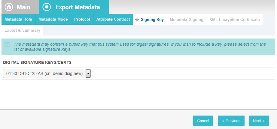
Click Next.
On the Metadata Signing screen, if you plan to sign the metadata file that will be exported, select the certificate that will be used to sign the file.
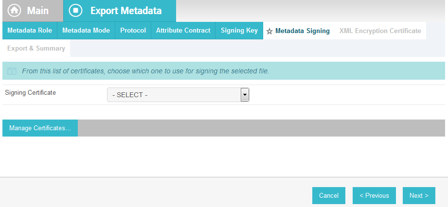
Click Next.
On the XML Encryption Certificate screen, select the certificate that the Identity Provider will use to encrypt XML messages.
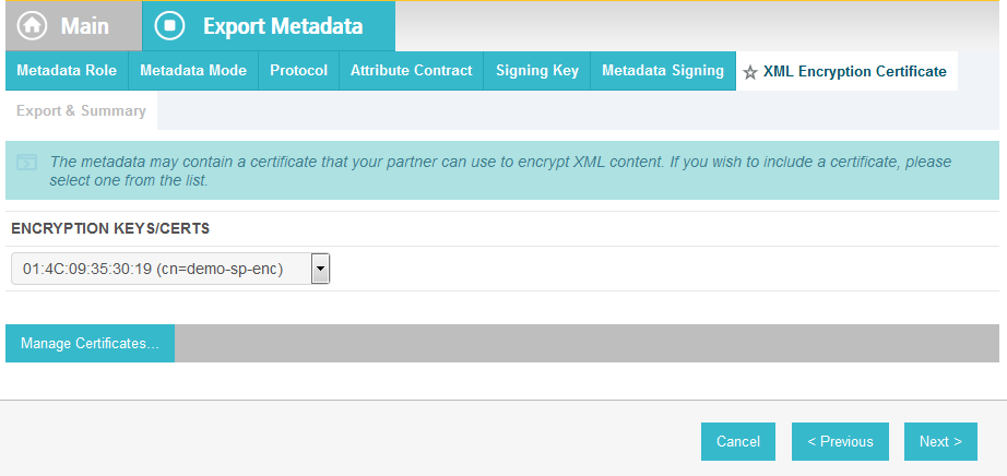
Click Next.
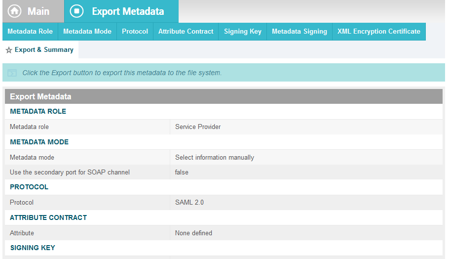
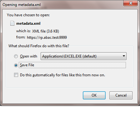
Click Export.
This will create an export file that contains the metadata of the RP, which you can download using the browser. This file will be used later in the section, when configuring the PingFederate-IDP.
2.10. Install PingFederate-IdP
This PingFederate installation in this section is for the PingFederate-IdP.
Log on to the server that will host the PingFederate service for the IdP, and follow the instructions at the link below to install PingFederate and run it as a Windows service.
https://documentation.pingidentity.com/display/PF73/Installation
2.11. Install the SCE Plug-in for the PingFederate-IdP
The SCE Plug-in integrates the features provided by RSA AA with PingFederate-IdP by providing a customizable user interface when RSA AA is accessed. New users will be enrolled into RSA’s enhanced security features and be prompted to provide information such as security questions, a phone number, email address, and an SMS-enabled device. Follow the instructions below to install the SCE Plug-in adapter for the IdP. The variable <PF-install> used in the instructions corresponds to the PingFederate installation path. In this build, the PingFederate installation path was c:\pingfederate-7.3.0.
Log on to the server that hosts the PingFederate service for the Identity provider.
Download the SCE Plug-in adapter jar file (e.g.,
sce-adapters-pingfederate-aa.1.1.jar) to the local PingFederate server.Copy the jar file to <PF-install>/server/default/deploy
From the adapter
dist/conf/templatefolder, copy all .html files to<PF-install>/server/default/conf/template.
From the adapter
dist/conf/template/assetsfolder, copy the aa folder to<PF-install>/server/default/conf/template/assets
From the adapter
dist/data/adapter-configfolder, copy the aa folder to<PF-install>/server/default/data/adapter-config
From the adapter
dist/libfolder, copy all .jar files to<PF-install>/server/default/lib
2.12. Install the Situational Context Connector for the PingFederate-IdP
The Situational Context Connector and a Session Validator must be installed. In this build, both are installed on the PingFederate-IdP Server.
2.12.1. Install Situational Context Connector
Log on to the server that hosts the PingFederate service for the Identity provider.
Download the Situational Context Connector integration zip file (e.g.,
Situational_Context_Connector_v21.zip) to the local PingFederate server.Stop the PingFederate service if it is running.
Unzip the integration kit distribution file (
Situational_Context_Connector_v21.zip) and copy the adapter file,pf.plugins.ise-idp-adapter.jar, from the /dist to the PingFederate “deploy” folder:<PF_install>\pingfederate\server\default\deploy
Create a new sub-directory under the PingFederate \deploy folder called “portal.”
<PF_install>\pingfederate\server\default\deploy\portal\
Create a new sub-directory under the new \portal\ directory called “gateway.”
<PF_install>\pingfederate\server\default\deploy\portal\gateway\
Copy the “index.jsp” from the Adapter .zip /dist folder to
<PF_install>\pingfederate\server\default\deploy\portal\gateway\
Edit the sessionIdCookie.setDomain parameter in the
index.jspfile to specify the cookie domain of your PingFederate server (Note: valid cookie domains must contain a minimum of two “dots.” For example “.company.com.”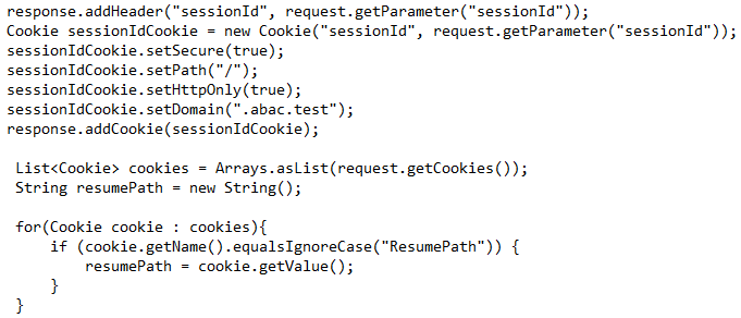
Start or restart the PingFederate server.
2.12.2. Install Situational Session Validator
On the same PingFederate-IdP server, unpack the contents of the
Situational_SessionValidator.zipfile found in the Context Connector integration kit zip file (Situational_Context_Connector_v21.zip).Navigate to the folder where you unpacked the Situational Session Validator and locate the
redirector.propertiesfile.Edit the values in the
redirector.propertiesfile according to your environment.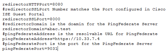
Note: As shown above, the redirectorSSLPort should be the same port number that you chose for the Guest Access Portal settings during the ISE configuration. For this build it is set to 8000.
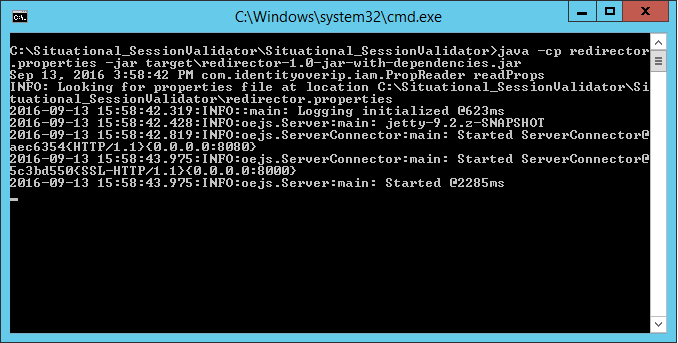
Start the session validator by running the runme script, runme.bat. Afterward, you will see a Command Prompt window pop up running the script.
2.13. Configure PingFederate-IdP
Follow the instructions in the subsections below to configure PingFederate as the Federation Server for the IdP.
Launch your browser and go to https://<DNS_NAME>:9999/pingfederate/app.
Replace DNS_NAME with the fully qualified name of the IdP’s PingFederate server (e.g., https://idp.abac.test:9999/pingfederate/app).
Log on to the PingFederate app using the credentials you configured during installation.
2.13.1. Configure SAML Protocol
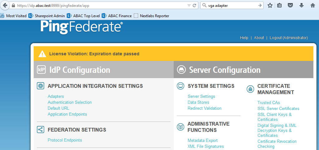
On the Main Menu under System Settings, click Server Settings.
Click the Roles and Protocols tab. Select Enable Identity Provider (IdP) role and support the following.
Select SAML 2.0.
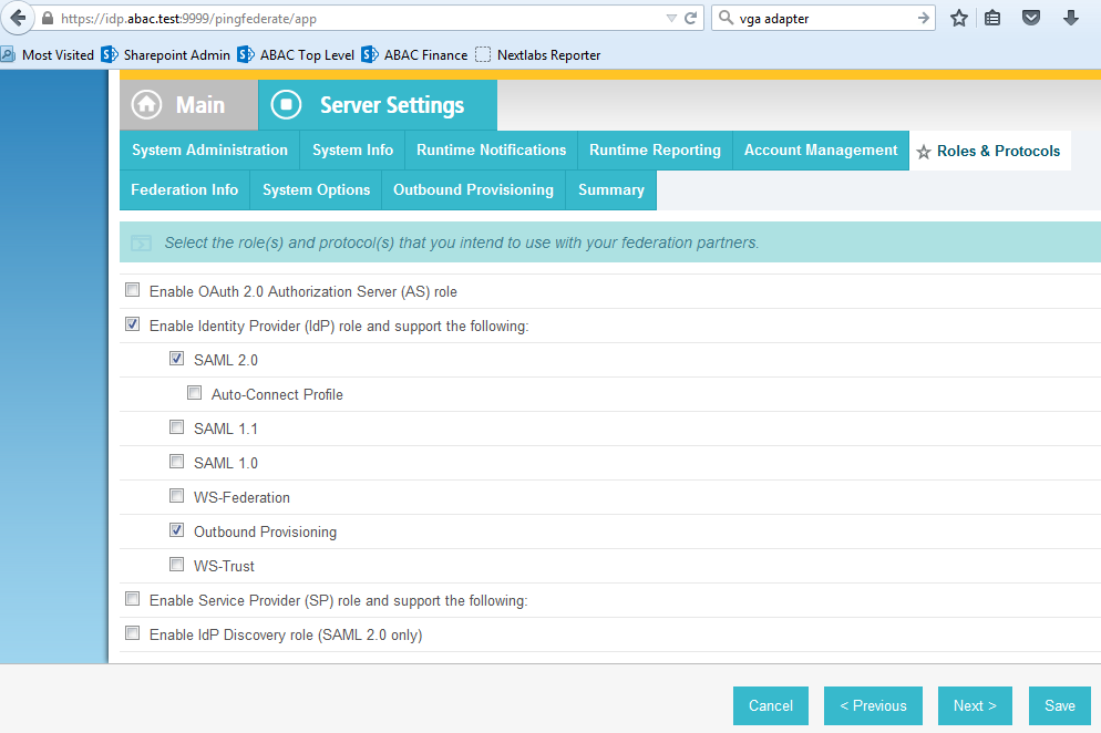
Click Save.
2.13.2. Create Data Store for Microsoft AD
On the Main Menu under System Settings, click Data Stores.
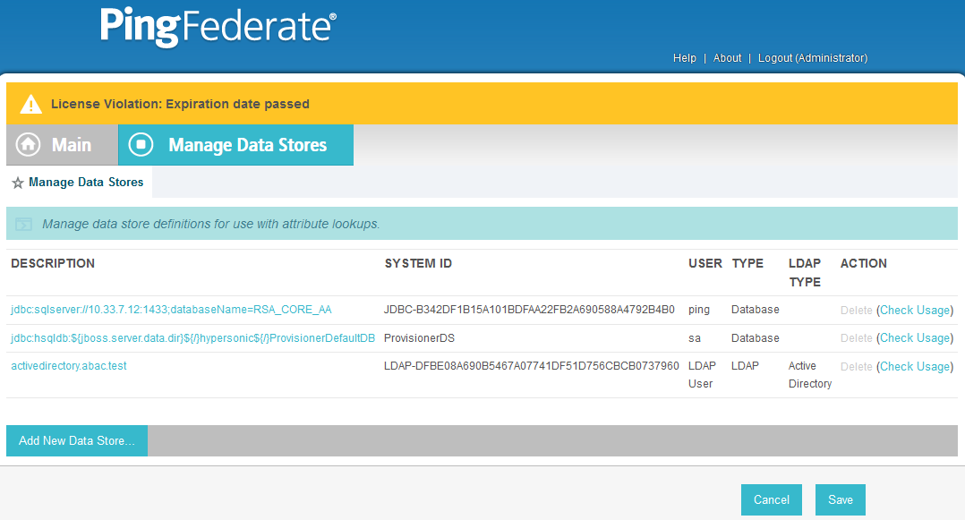
Select LDAP.
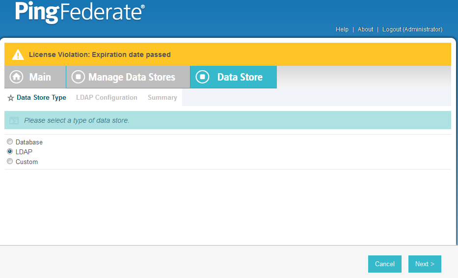
Click Next.
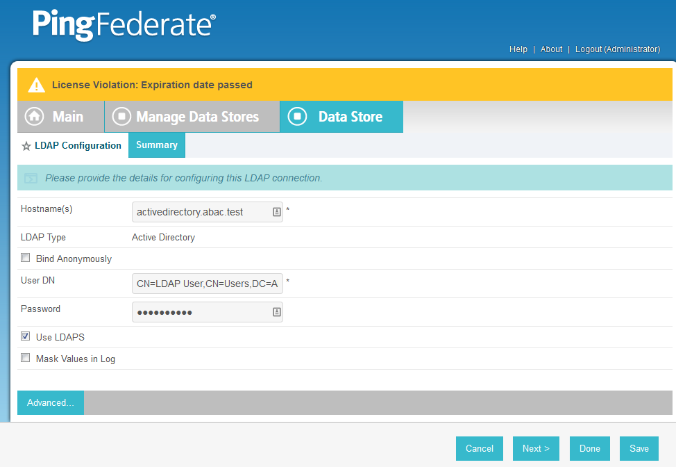
Enter the Hostname where the Microsoft AD is hosted (e.g., activedirectory.abac.test).
For the LDAP Type, select Active Directory.
Enter the User DN created in the earlier section named Create the LDAP User for Federated Authentication (e.g., CN=LDAP User, CN=Users,DC=ABAC,DC=Test).
Enter the password associated with the LDAP User DN. Select the option to use LDAPS.
Click Next. Then, click Save on the Summary screen.
2.13.3. Create Credential Validator for Microsoft AD
On the Main Menu under Authentication, click Password Credential Validators.
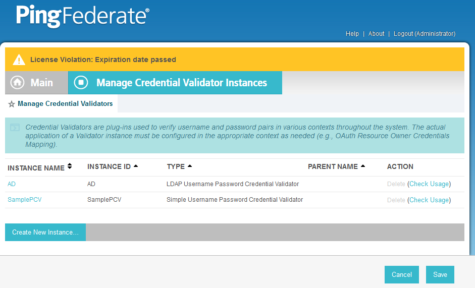
Click Create New Instance.
Enter a unique Instance Name you would like to use to refer to this configuration (e.g., AD username password).
Enter a unique Instance Id (typically the same as the Instance Name) without any spaces.
For Type, select LDAP Username Password Credential Validator.
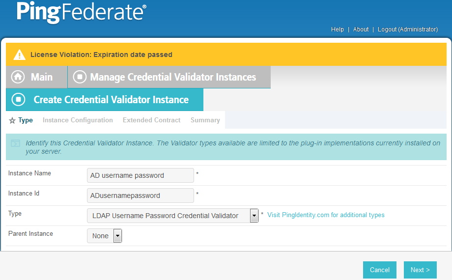
Click Next.
For the LDAP DATASTORE, select the Active Directory data store you created earlier (e.g., activedirectory.abac.test).
Enter the SEARCH BASE (location in the directory where the LDAP search begins) for your Microsoft AD LDAP directory (e.g., DC=ABAC,DC=TEST).
Enter the SEARCH FILTER (e.g., sAMAccountName=${username}. The SEARCH FILTER allows Ping to search the LDAP directory, looking for a match where the attribute named sAMAccountName matches the username value passed from the PingIdentity server.
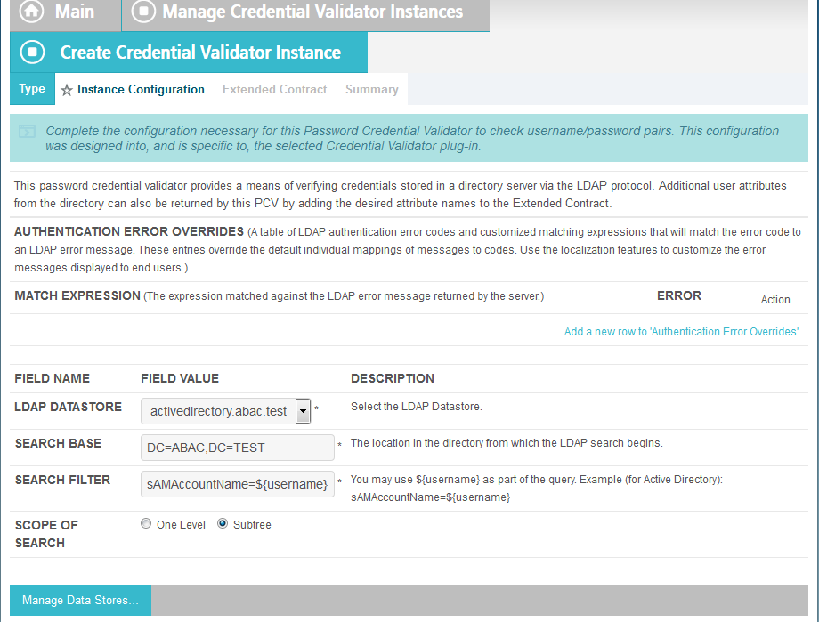
Click Next.
You should see two attributes listed under CORE CONTRACT, DN, and username.
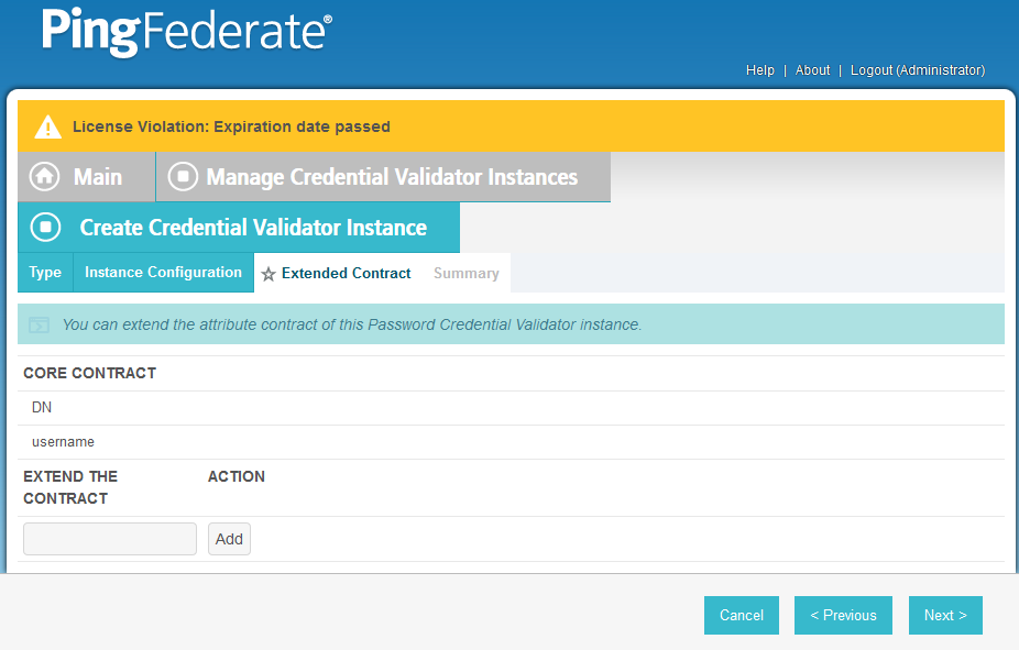
Click Next.
You should see a summary page.
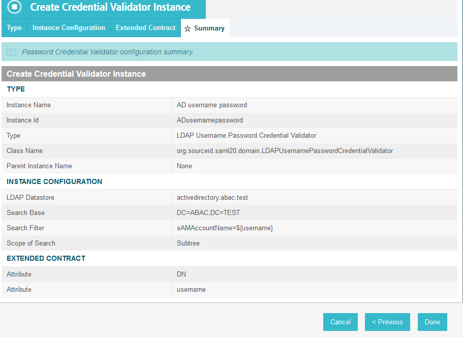
Click Done.
You should see a list of the credential validator instances, including the newly added validator (e.g., AD username password).
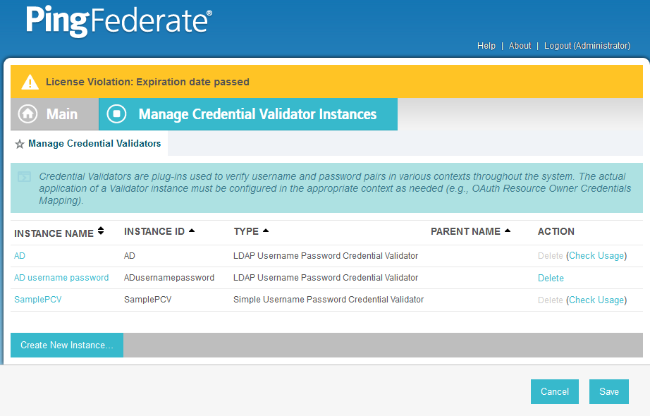
Click Save to complete configuration of the credential validator.
2.13.4. Create IdP Adapter for Authentication with Microsoft AD via Web Browser Form
The IdP Adapter created in this section is the logical component PingFederate uses to authenticate a user with Microsoft AD via a web browser login page.
On the Main Menu under Application Integration Settings, click Adapters.
Click Create New Instance.
In Instance Name, enter a unique name for the instance. The name will be used to refer to this configuration (e.g., AD HTML forms).
Enter a unique Instance Id (typically the same as the instance name) without any spaces. For Type, select HTML Form IdP Adapter.
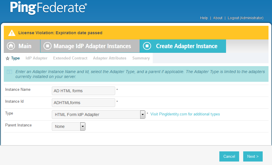
Click Next.
Under PASSWORD CREDENTIAL VALIDATOR INSTANCE, click on the Add a new row to Credential Validator’s hyperlink. This will add a new selection box under the PASSWORD CREDENTIAL VALIDATOR INSTANCE with the value of “—Select One—“ in it. In that new box, select the credential validator for Microsoft AD that was created in an earlier section (e.g., AD username password).
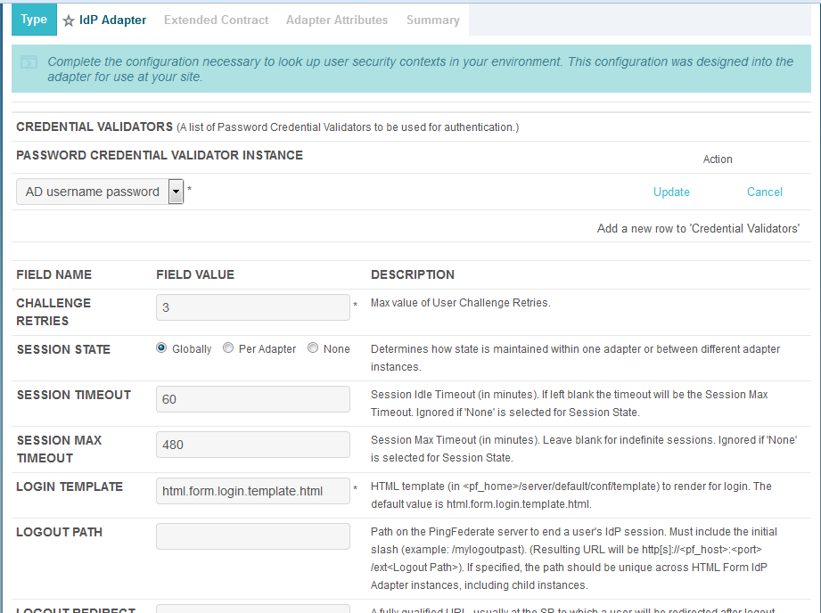
Under PASSWORD CREDENTIAL VALIDATOR INSTANCE, click the Update hyperlink on the right side of the page. This will cause the selection box to turn grey.
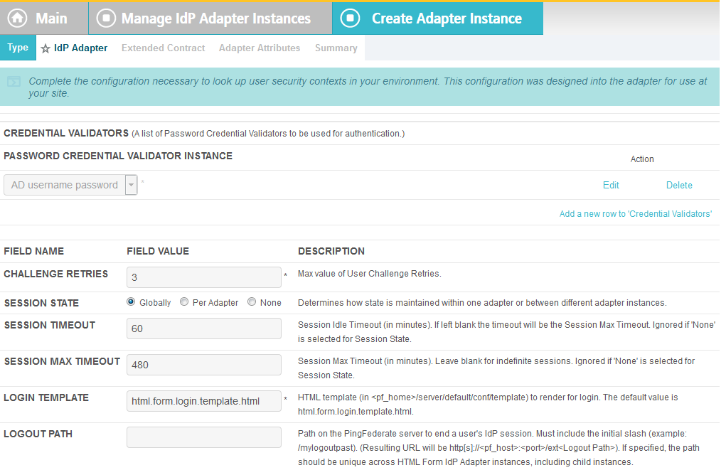
Click Next. Then, click Next again to bypass the Extended Contract screen.
On the Adapter Attributes screen, select the PSEUDONYM check box in the username row.

Click Next. On the Summary screen, click Done.
- Click Save to complete configuration of the new adapter.
2.13.5. Create IdP Adapter for Two-Factor Authentication with RSA AA
The IdP Adapter created in this section is the logical component PingFederate uses to authenticate a user with RSA AA using a second factor.
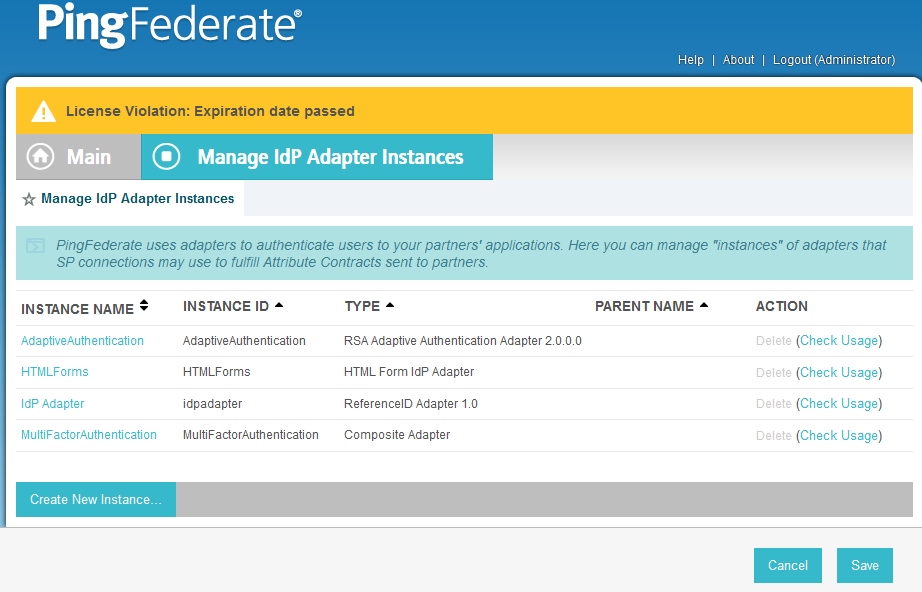
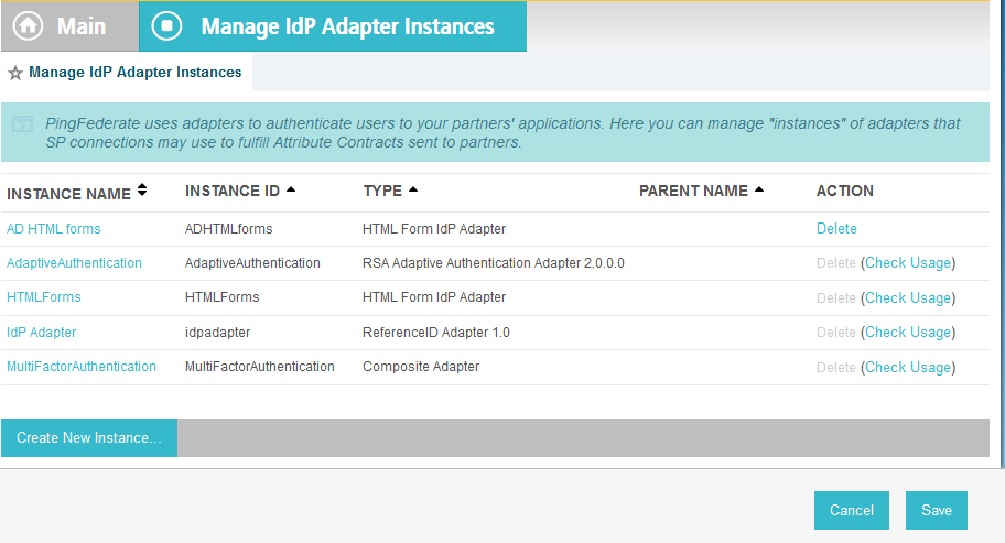
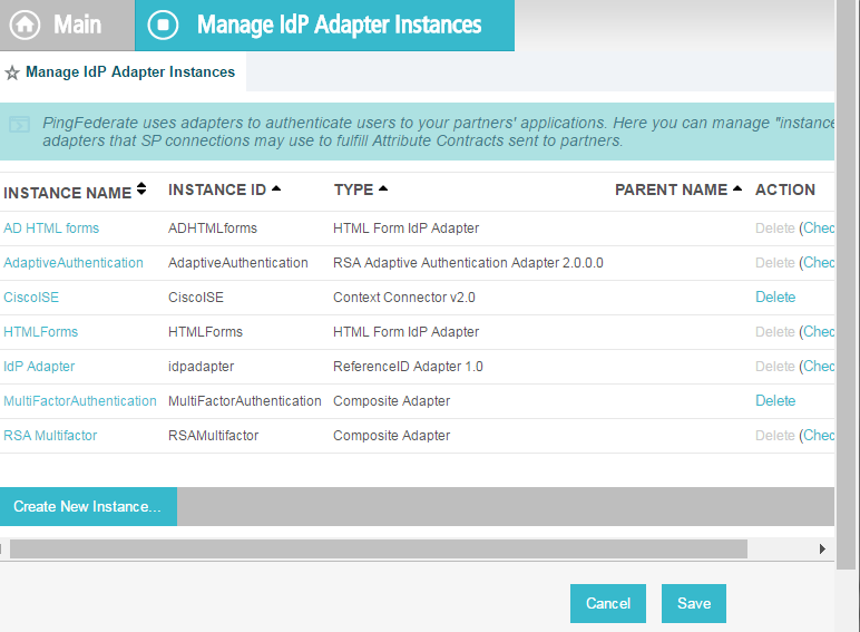
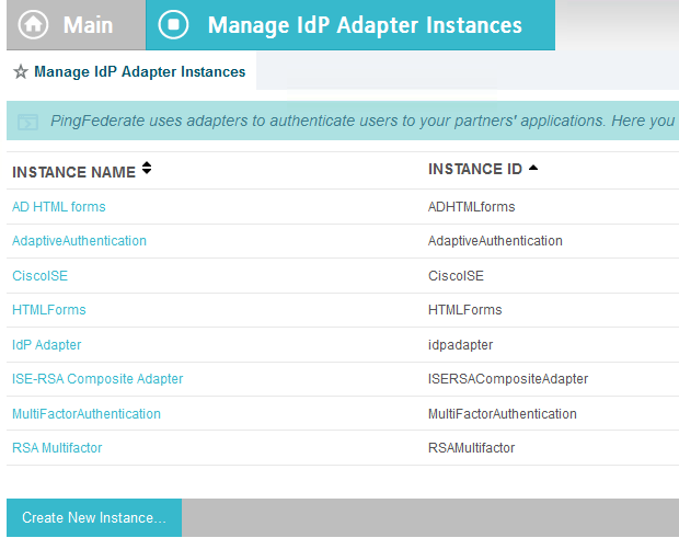
On the Main Menu under Application Integration Settings, click Adapters.
On the Manage IdP Adapters screen, click Create New Instance.
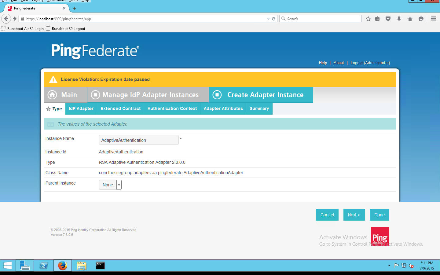
On the Type screen, enter an Instance Name and Instance ID.
Set the following settings on the Adapter Type page before clicking Next:
- Instance Name: (Instance Name)
- Instance ID: (Instance ID)
- Type: RSA Adaptive Authentication Adapter 2.0
- Class Name: com.thescegroup.adapters.aa.pingfederate.AdaptiveAuthenticationAdapter
- Parent Instance: None
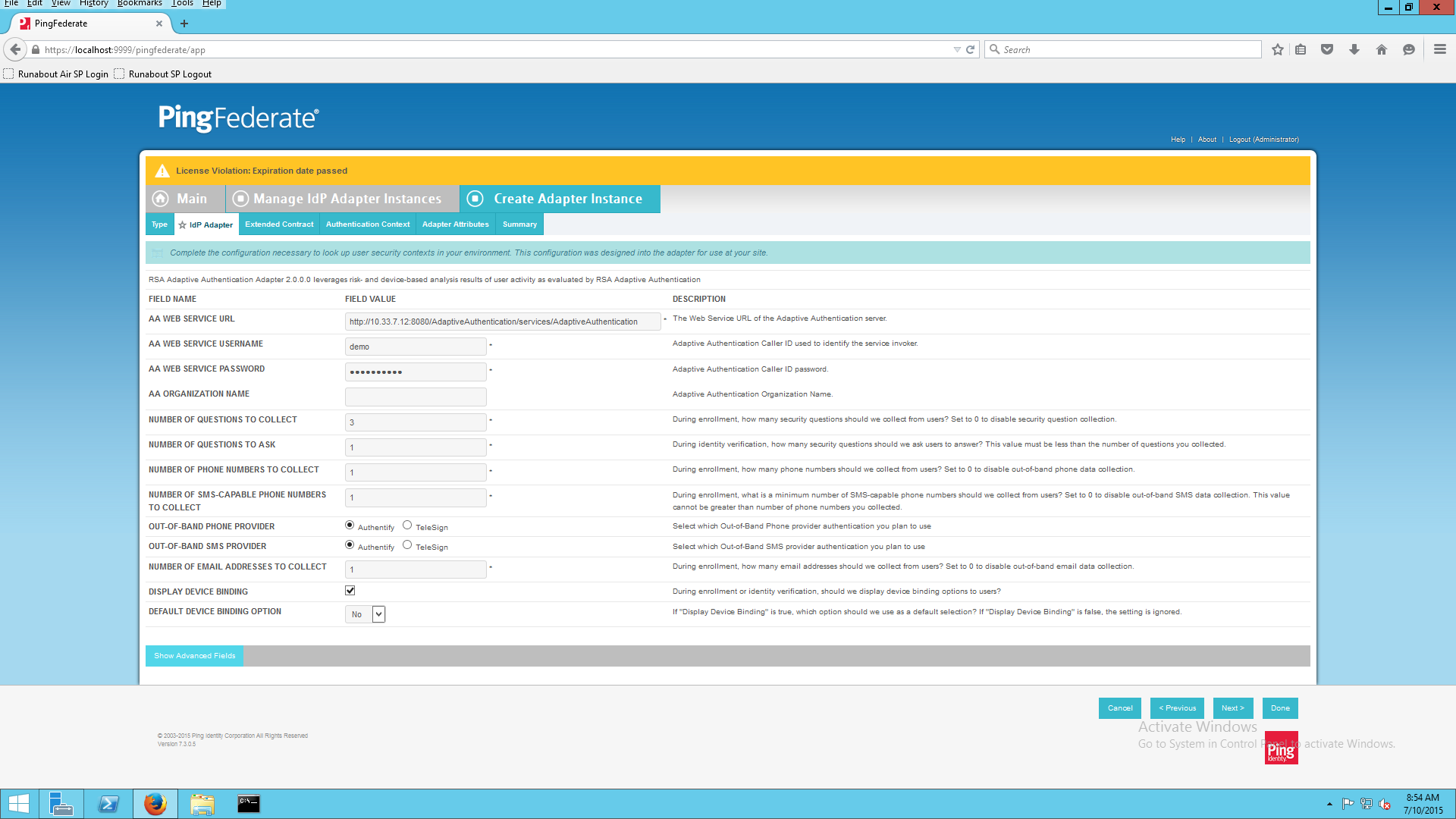
On the IdP Adapter configuration page, click Show Advanced Fields and input the following parameters while leaving the rest as default, before clicking Next:
- AA Web Service URL: http://<RSA Server DNS>:8080/AdaptiveAuthentication/services/AdaptiveAuthentication
- AA Web Service Username: [username] (Credentials must match on RSA server.)
- AA Web Service Password: [password]
On the Extended Contract screen, type transactionid (all lowercase). Then, click Add. By default, username should already be listed under Core Contract.
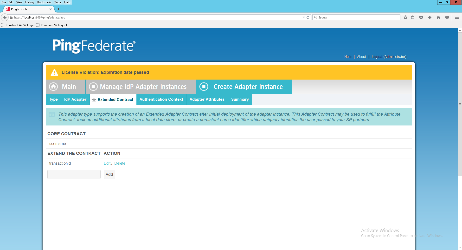
Click Next.
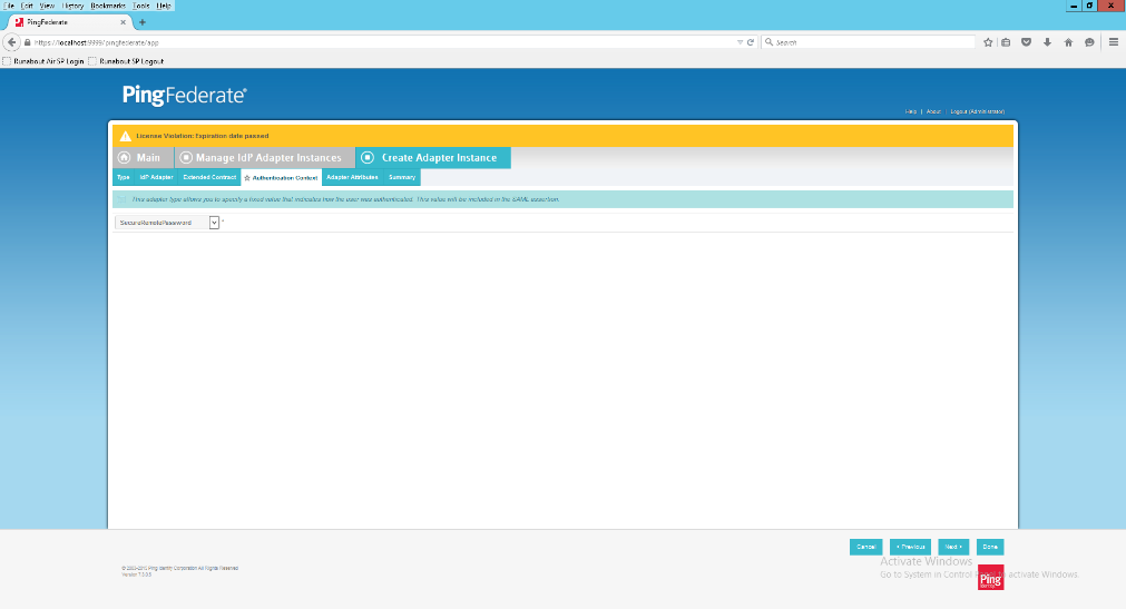
On the Authentication Context screen, select SecureRemotePassword as the fixed value for authentication. This value will be included in the SAML assertion. Click Next.
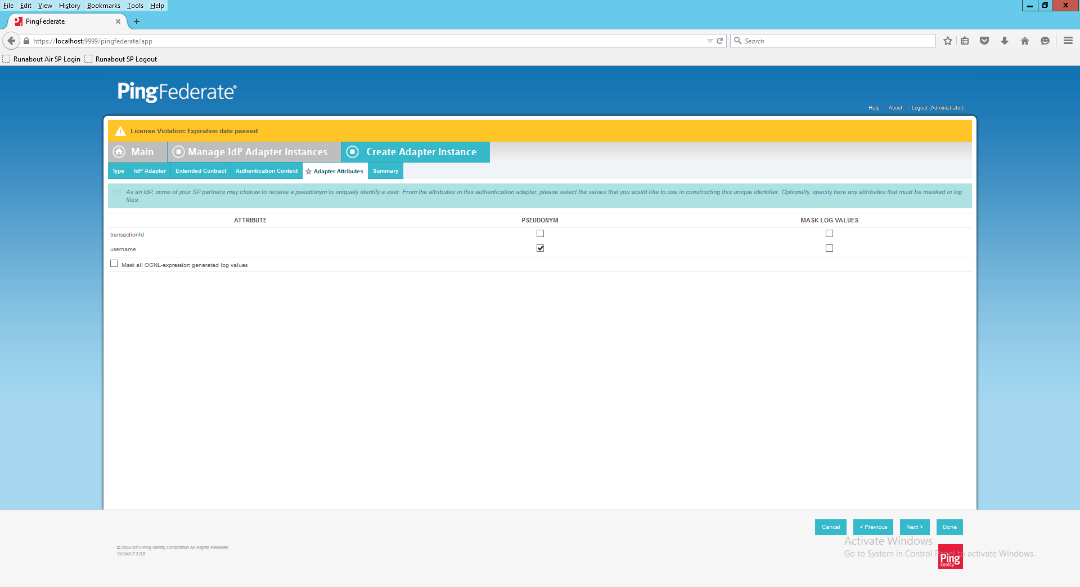
On the Adapter Attributes screen, select username as the Pseudonym. Click Next.
On the Summary screen, verify that the information is correct and click Done.
On the Manager IdP Adapter Instances screen, click Save to complete the Adapter configuration.
2.13.6. Create Composite IdP Adapter Integrating Microsoft AD and RSA AA
The IdP Adapter created in this section is a composite adapter that integrates the two previously created adapters for Microsoft AD and RSA AA. When a user is directed to the PingFederate IdP server, the user will see a web form where they can enter their Microsoft AD credentials. Following authentication with Microsoft AD, PingFederate will initiate the second factor authentication with an SCE Plug-in. The SCE Plug-in will then present the user with a request for the second factor.
On the Main menu under Application Integration Settings, click Adapters.
On the Manage IdP Adapters screen, click Create New Instance.
Enter a unique Instance Name you would like to use to refer to this configuration (e.g., RSA Multifactor).
Enter a unique Instance Id (typically the same as the Instance Name) without any spaces.
For Type, select Composite Adapter.
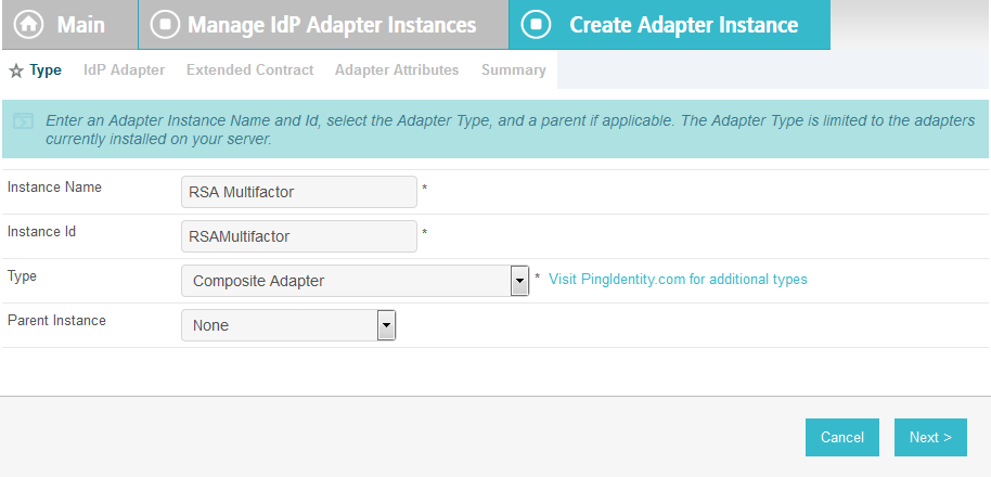
Click Next.
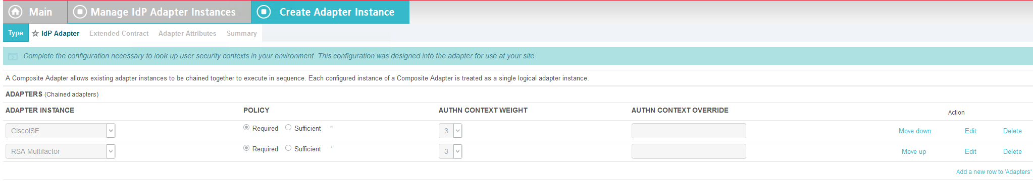
On the IdP Adapter screen, under ADAPTER INSTANCE, click on the Add a new row to ‘Adapters’s hyperlink. This will add a new selection box under the ADAPTER INSTANCE with the value of “—Select One—“ into the box. In that new box, select the adapter instance for HTML forms with Microsoft AD that was created in an earlier section (e.g., AD HTML forms).
Under ADAPTER INSTANCE, click the Update hyperlink on the right side of the page. This will cause the selection box to turn grey.
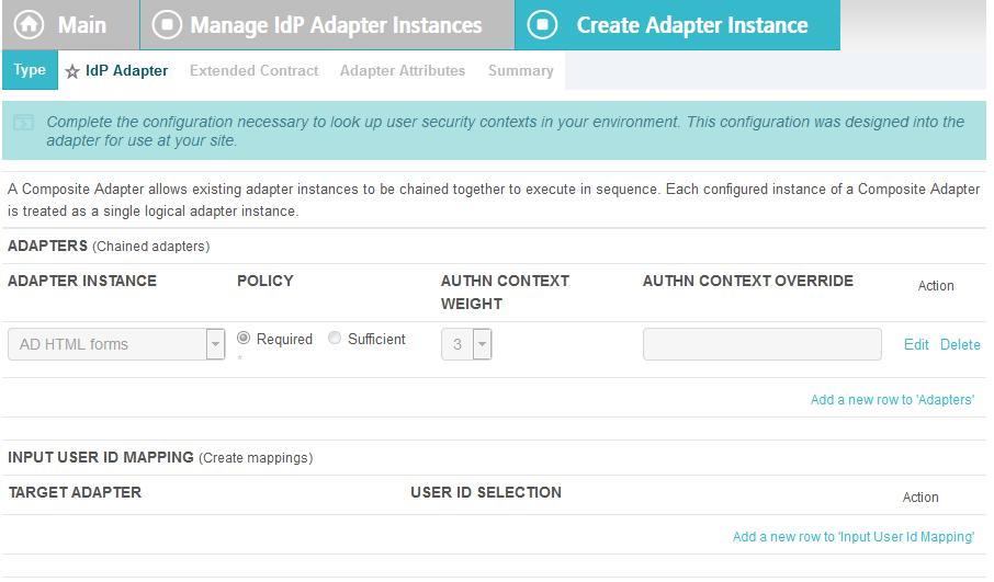
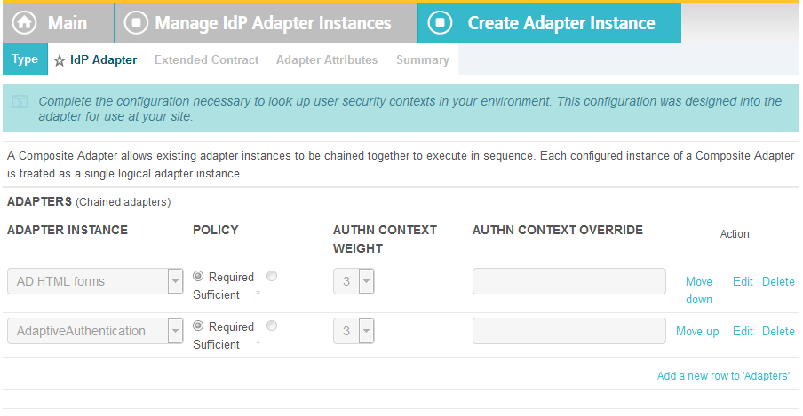
Repeat the previous steps to add another row to Adapters using the hyperlink on the right side of the page. This time, select the AdaptiveAuthentication adapter in the selection box. When complete, the IdP Adapter screen will look similar to the screenshot below, with two adapters configured under ADAPTER INSTANCE.
Under TARGET ADAPTER, click on the Add a new row to ‘Input User Id Mapping’ hyperlink. This will add a new selection box under the TARGET ADAPTER with the value of “—Select One—“ in the box.
In that new box, select the adapter instance for the RSA authentication that was created in an earlier section (e.g., AdaptiveAuthentication).
In the new USER ID SELECTION box, select username.
Under TARGET ADAPTER, click the Update hyperlink on the right side of the page. This will cause the selection box to turn grey.

Click Next.
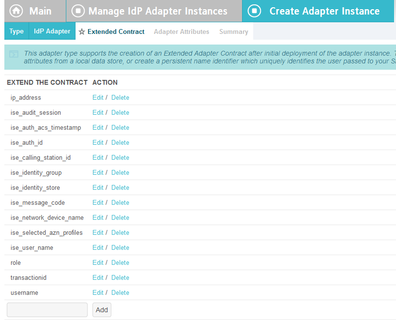
On the Extended Contract screen, enter the value username in the EXTEND THE CONTRACT field.
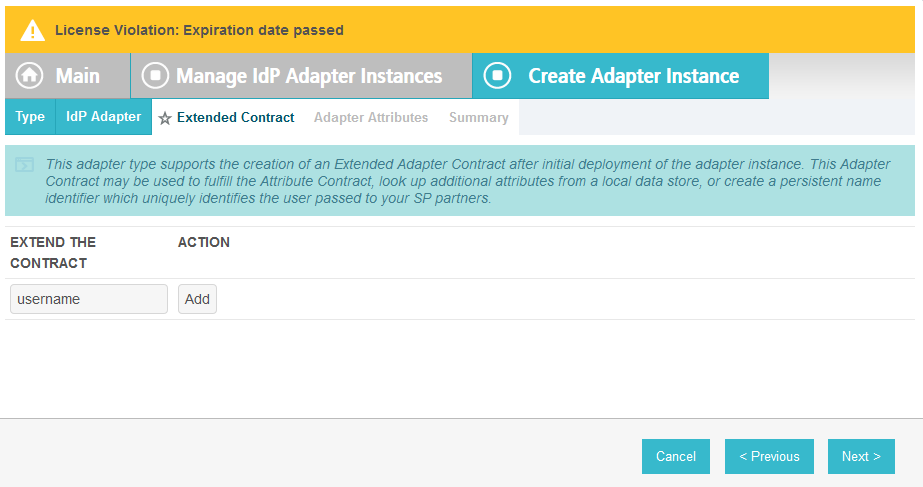
Click Add. Enter the value transactionid (all lowercase) in the EXTEND THE CONTRACT field.
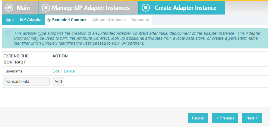
Click Add. Then, click Next.
On the Adapter Attributes screen, in the username row, select the PSEUDONYM column.
Click Next. On the Summary screen, click Done.
Click Save to complete configuration of the new composite adapter.
2.13.7. Create IdP Adapter for the Situational Context Connector and ISE Authentication
The IdP Adapter created in this section is the logical component PingFederate uses to obtain connection (device and network) information obtained from ISE Authentication via the Situational Context Connector. These device and network attributes serve as environmental attributes in this build.
On the Main menu under Application Integration Settings, click Adapters.
On the Manage IdP Adapters screen, click Create New Instance.
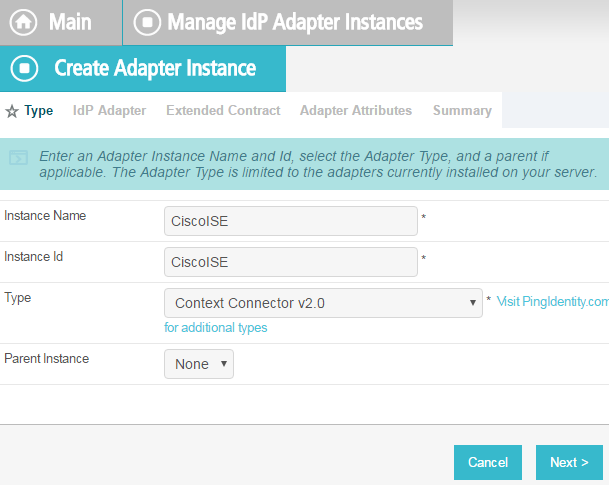
On the Type screen, enter an Instance Name and Instance ID.
For Type, select Context Connector v2.0, and click Next.
Enter configuration information and click Next.

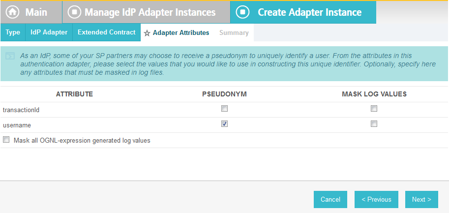
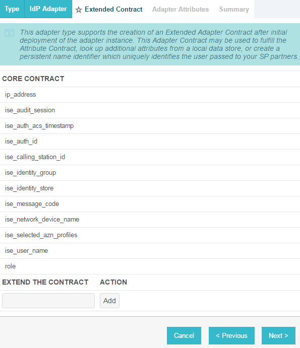
On the Extended Contract screen, you can configure additional attributes for the adapter. We retained the defaults and clicked Next.
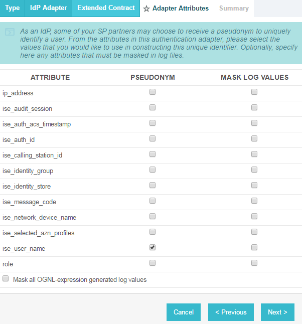
On the Adapter Attributes screen, in the row for ise_username, check the box in the Pseudonym column. Click Next. (Note: if you added other attributes in Step #6, you could check the box under Pseudonym for those as well.)
On the Summary screen, review the configuration and scroll down to click Done.
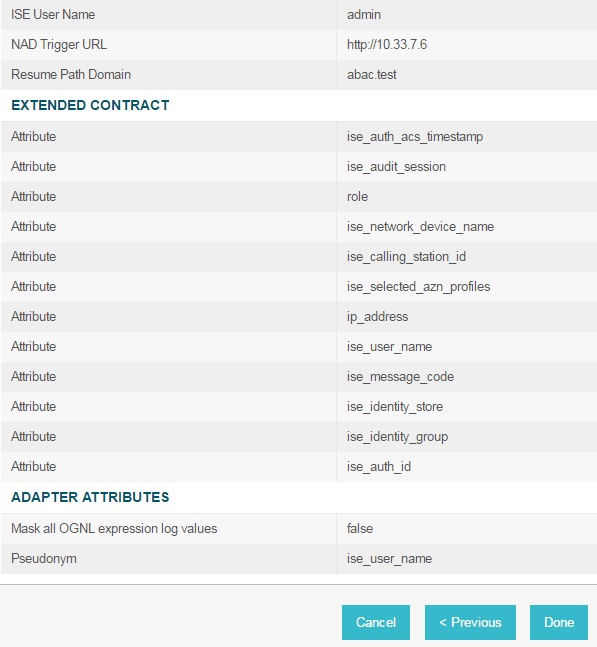
On the Manage IdP Adapter Instances screen, click Save.
2.13.8. Configure the Federation Connection to the Relying Party
This PingFederate SP Connection at the PingFederate-IdP will configure the SAML exchange with a server in the RP’s environment. This connection will also enable a user to authenticate using the composite adapter created in the previous section.
On the Main Menu under SP CONNECTIONS, click Create New.
On the Connection Type screen, make sure Browser SSO Profiles is selected.
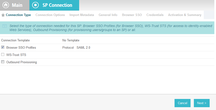
Click Next. On the Connection Options screen, make sure Browser SSO is selected.
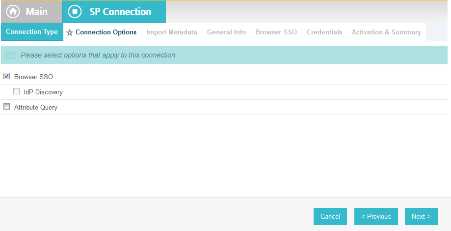
Click Next.
On the Import Metadata screen, click Browse and select the metadata file that you exported from the RP’s PingFederate server.
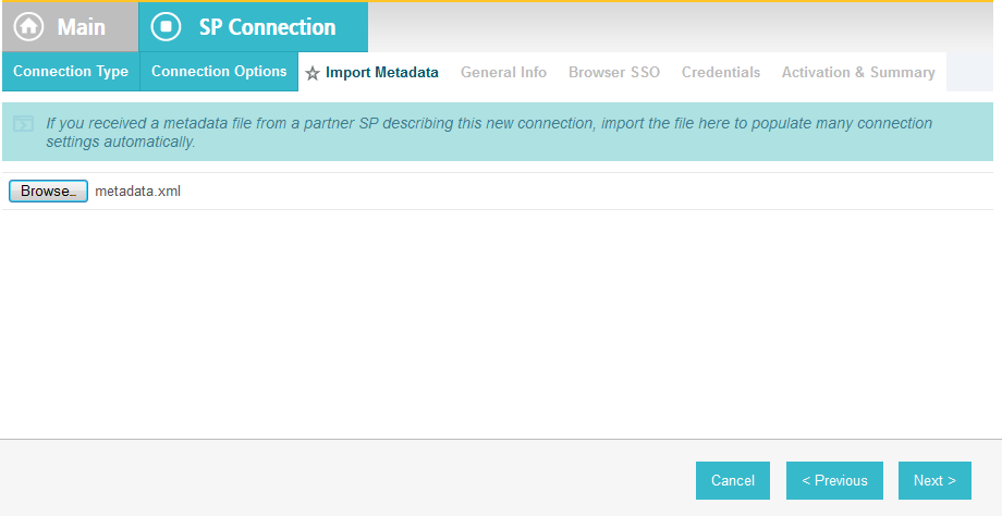
Click Next.
On the Metadata Summary screen, click Next.
On the General Info screen, you should see some configuration information (e.g., Base URL) about the RP that was taken from the metadata file that you selected earlier.
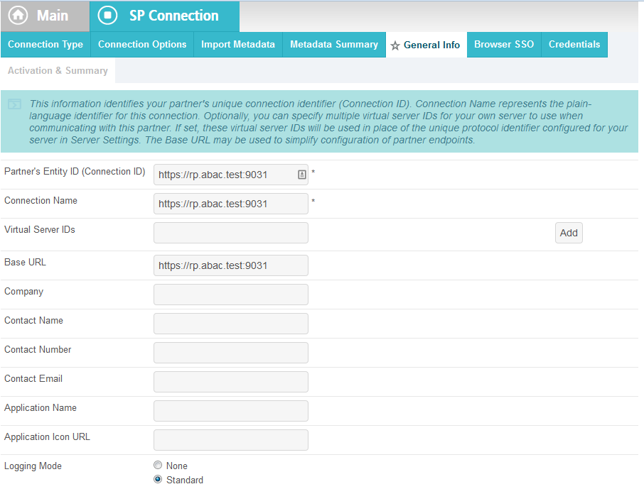
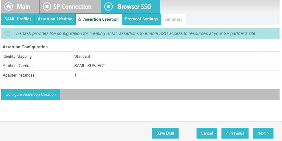
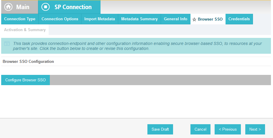
Click Next. On the Browser SSO screen, click Configure Browser SSO.
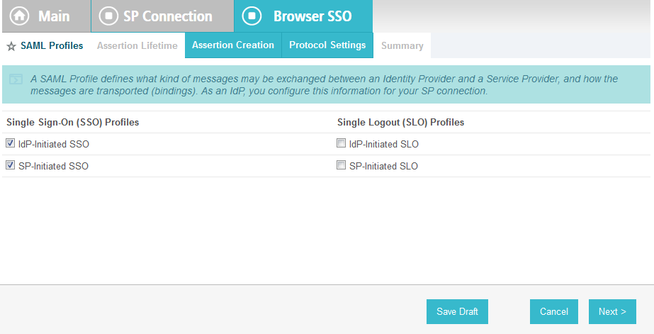
Select IdP-Initiated SSO and SP-Initiated SSO. Then, click Next.
On the Assertion Lifetime screen, click Next.
On the Assertion Creation screen, click Configure Assertion Creation. This will bring up a sequence of sub-screens, starting with the Identity Mapping screen.
On the Identity Mapping screen, select the Standard option.
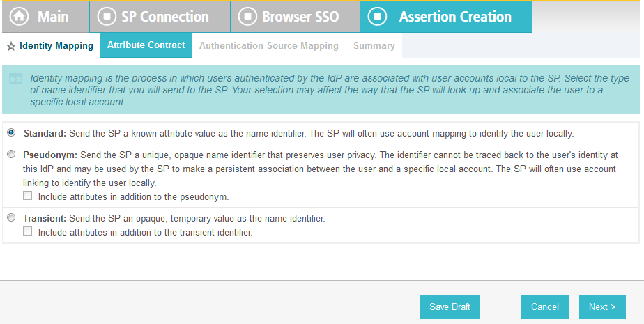
Click Next. This will bring up the Attribute Contract screen.
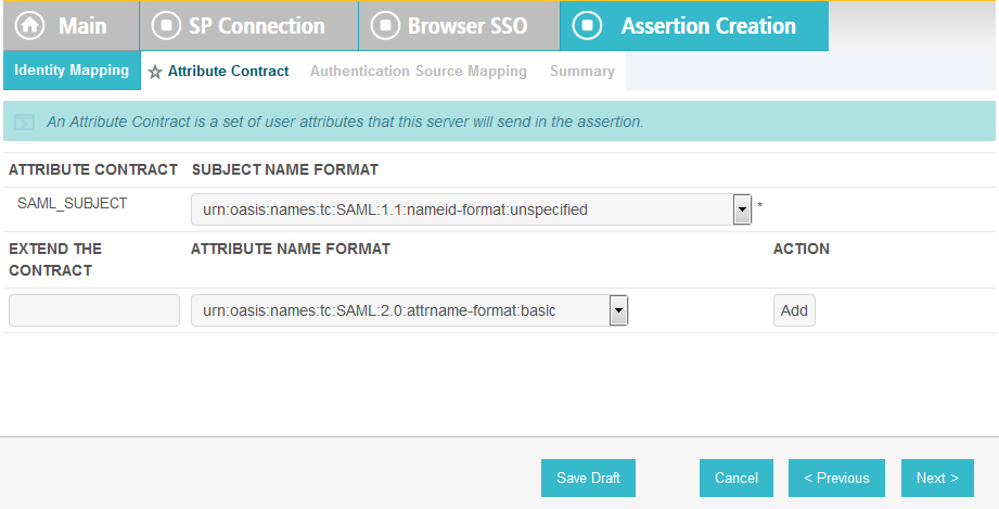
Click Next.
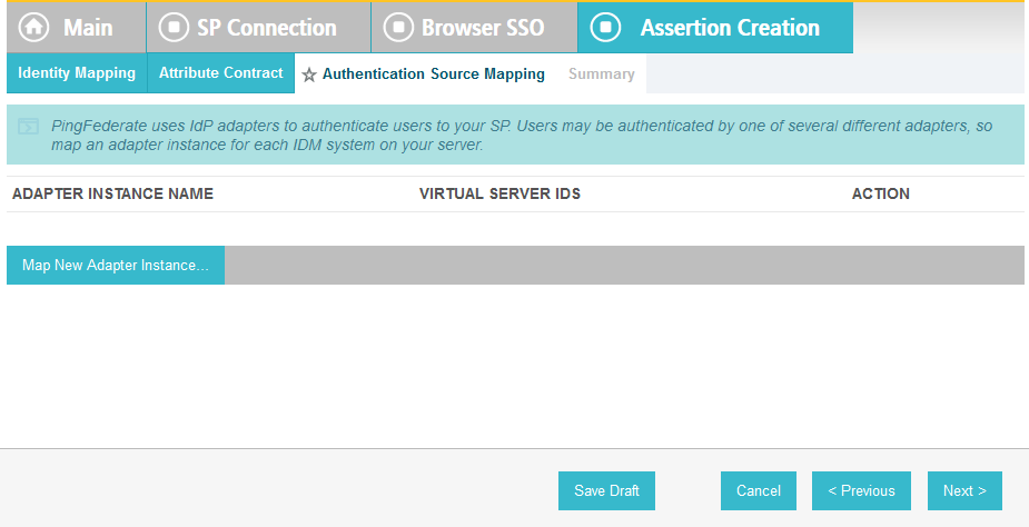
On the Authentication Source Mapping screen, click Map New Adapter Instance. This will launch a sequence of sub-screens, beginning with the Adapter Instance screen.
On the Adapter Instance screen, select the composite adapter created in an earlier section (e.g., RSA Multifactor).
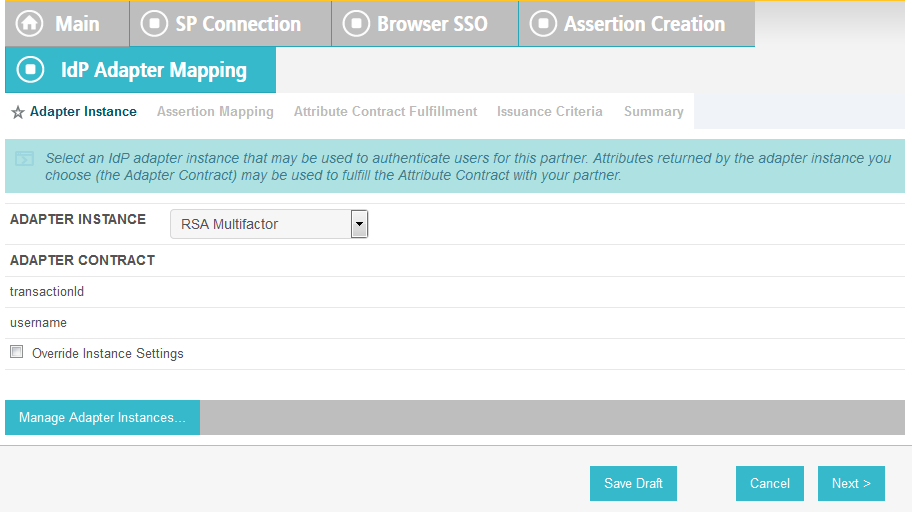
Click Next. On the Assertion Mapping screen, select Use only the Adapter Contract values in the SAML assertion.
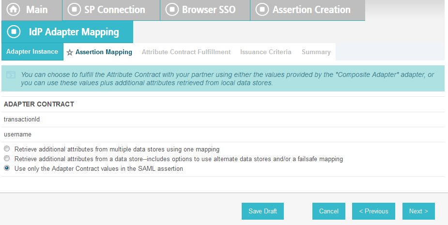
Click Next.
On the Attribute Contract Fulfillment screen, for SAML_SUBJECT, select Adapter for the SOURCE field and username for the VALUE field.
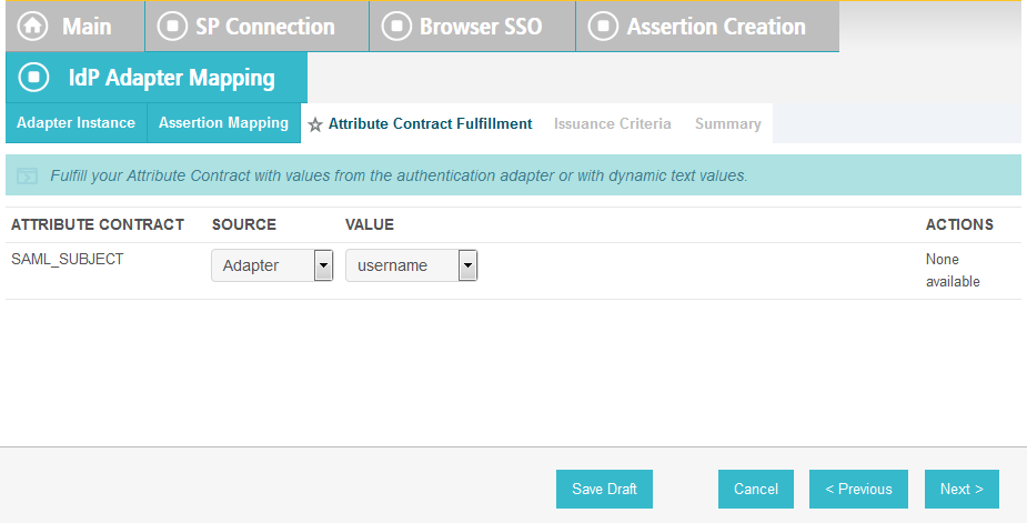
Click Next.

Click Next.
Click Done. This will bring you back to the Authentication Source Mapping screen, and you should see the composite adapter (e.g., RSA Multifactor) listed.

Click Next.
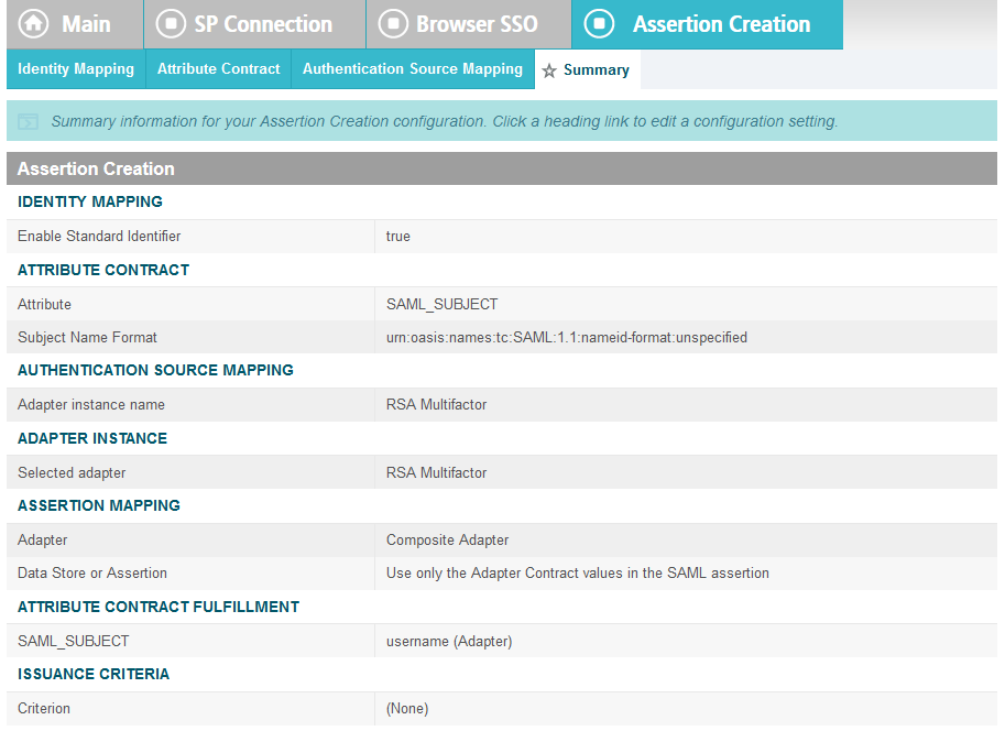
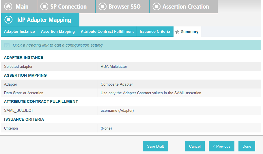
On the Summary screen, click Done. This will take you back to the Configure Assertion Creation screen.
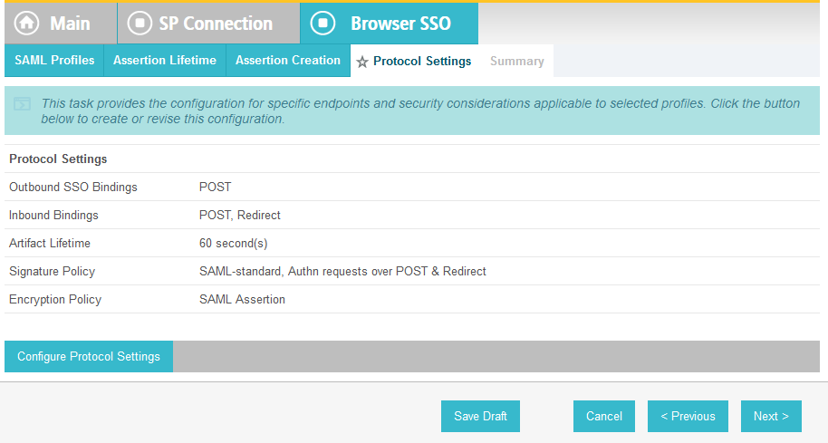
Click Next.
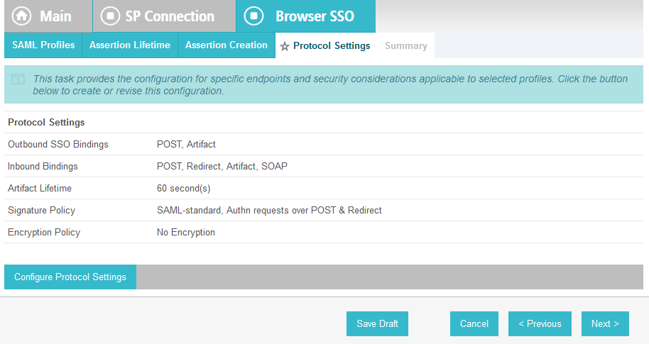
On the Protocol Settings screen, click Configure Protocol Settings. This will launch a sequence of sub-screens, beginning with the Assertion Consumer Service URL screen.
On the Assertion Consumer Service URL screen, make sure that the BINDING field is set to POST and the ENDPOINT URL field is set to /sp/ACS.saml2.
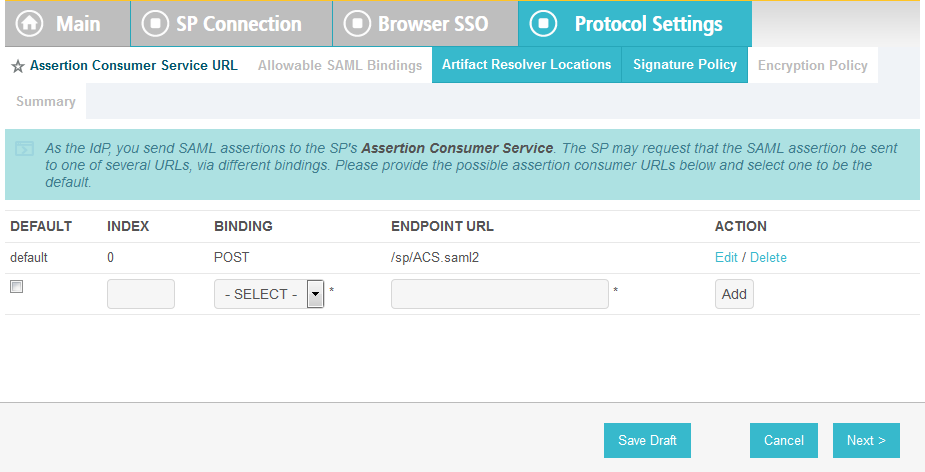
Click Next.
On the Allowable SAML Bindings screen, select POST and Redirect.
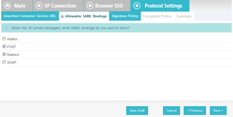
Click Next.
On the Signature Policy screen, select Require AuthN requests to be signed when received via the POST or Redirect bindings.

Click Next. On the Encryption Policy screen, select The entire assertion.
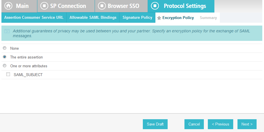
Click Next.
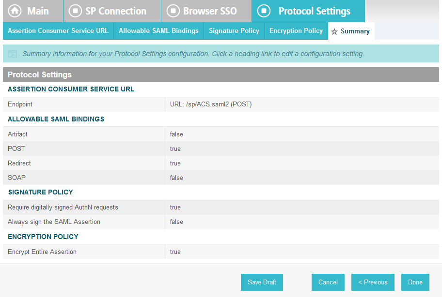
On the Summary screen, click Done.
This will take you back to the Protocol Settings screen.
Click Next.
On the Summary screen, click Done.
This will take you back to the Browser SSO screen.
Click Next.
On the Credentials screen, click Configure Credentials.
For the Signing Certificate field, select the certificate to be used to sign the SAML message.
Select the certificate that you configured for the server in an earlier section.
Select the Signing Algorithm for your environment (e.g., RSA SHA256).

Click Next.
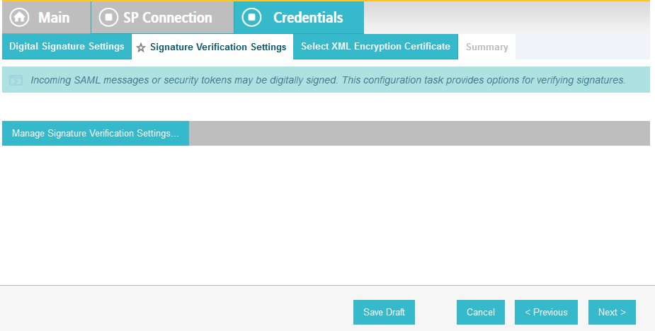
Click Next.
On the Select XML Encryption Certificate screen, select the Block Encryption Algorithm (e.g., AES-128), and the Key Transport Algorithm (e.g., RSA-OAEP).
For the selection box above the Manage Certificates button, select the RP’s public key certificate to be used to encrypt the message content.
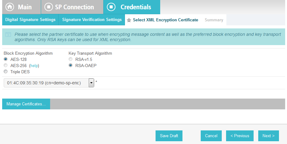
Click Next.
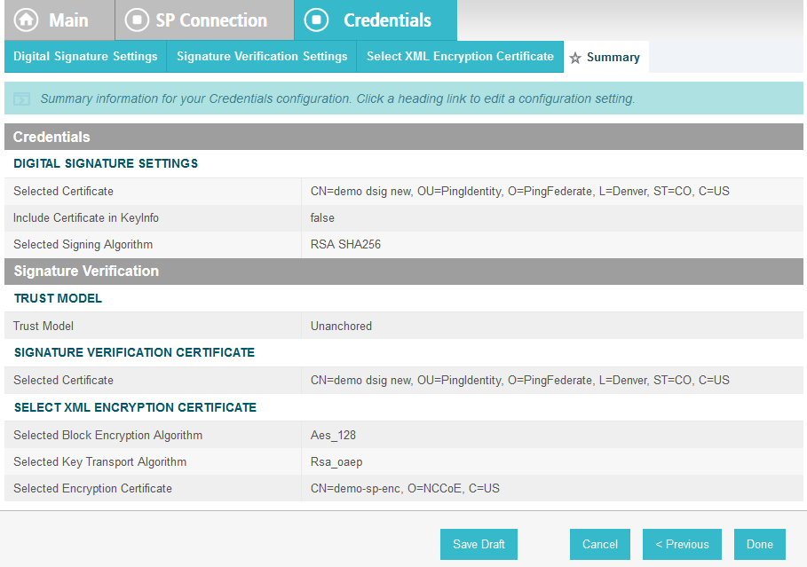
On the Summary screen, click Done. This will take you back to the Credentials screen.

Click Next.
On the Activation & Summary screen, select Active for the Connection Status field.
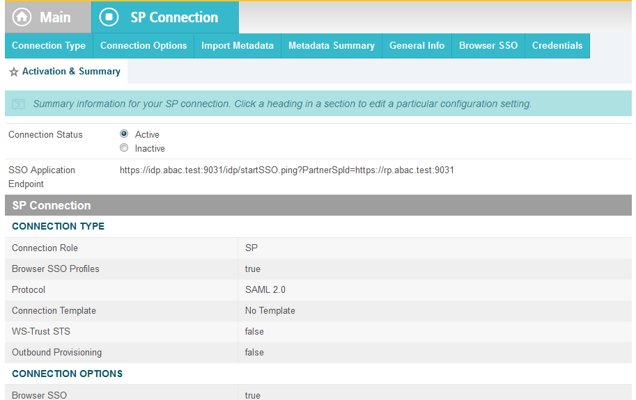
Copy the Identity Provider’s SSO Application Endpoint URL (e.g., https://idp.abac.test:9031/idp/startSSO.ping?PartnerSpId=https://rp.abac.test:9031) to the clipboard and save it to a text file, because this URL will be used in the Functional Test section.
Click Done. This will take you to a screen that lists the connections for the server, including the new connection you just created. Click Save to complete the configuration.
2.13.9. Configure ISE Composite Adapter
From the Main page, click on Adapters.
Click Create New Instance.
In the Instance Name field, enter ISE-RSA Composite Adapter.
In the Instance ID field, give the same name without spaces.
In the Type field, choose Composite Adapter.
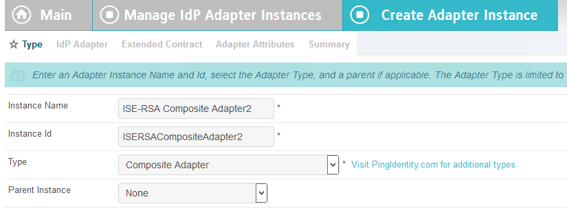
Click Next.
Click Add a new row to ‘Adapters’.
Choose CiscoISE.
Click Update.
Click Add a new row to ‘Adapters’.
Choose RSA Multifactor.
Click Update.
Click Next.
Add the attributes from both the ISE and RSA adapters.
Click Next.
Check the Pseudonym box next to username.

Click Next.
Click Done.
Click Save.
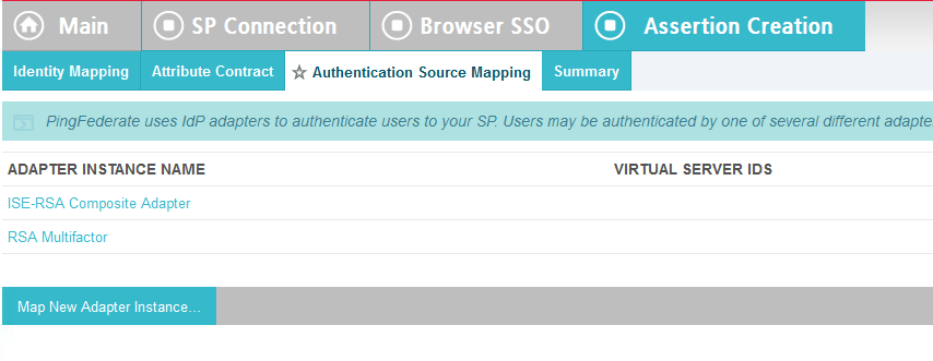
2.13.10. Applying the Composite Adapter
From the main page, click on rp.abac.test under SP Connections.

Scroll down and click on Authentication Source Mapping.

Click on Map New Adapter Instance.
In the Adapter Instance box, select the composite adapter.
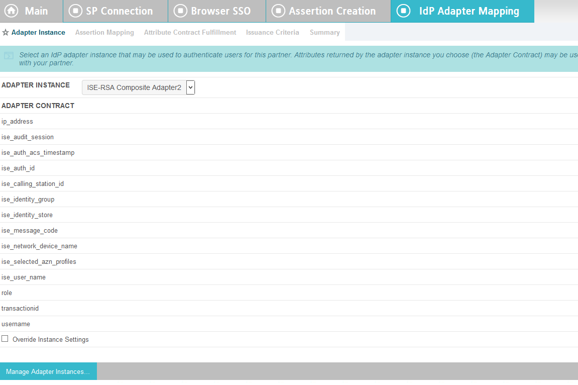
Click Next.
Select the top radio button labeled Retrieve additional attributes from multiple data stores using one mapping.
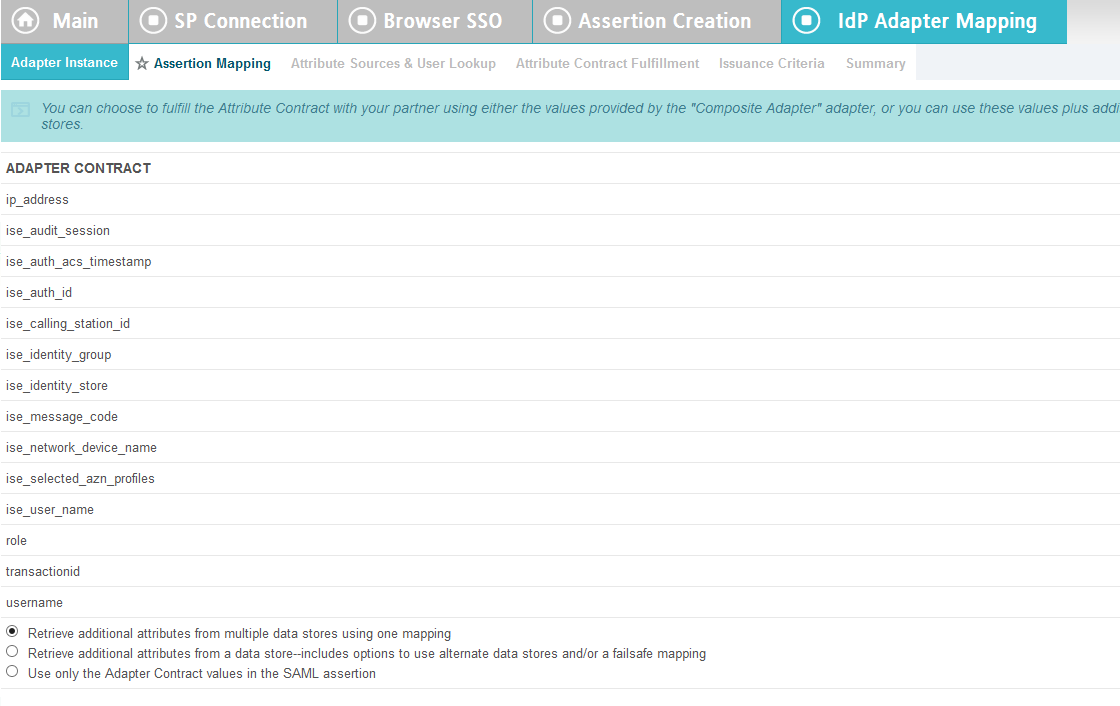
Click Next.
Click Add Attribute Source.
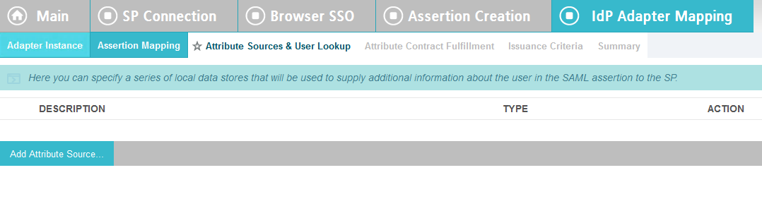
Enter ActiveDirectory for Source Id and Description.
Select activedirectory.abac.test in the Active Data Store drop-down.
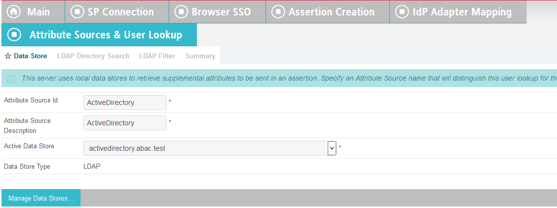
Click Next.
In the BaseDN field, enter DC=ABAC,DC=TEST.
Add all of the attributes from the LDAP Directory Search.
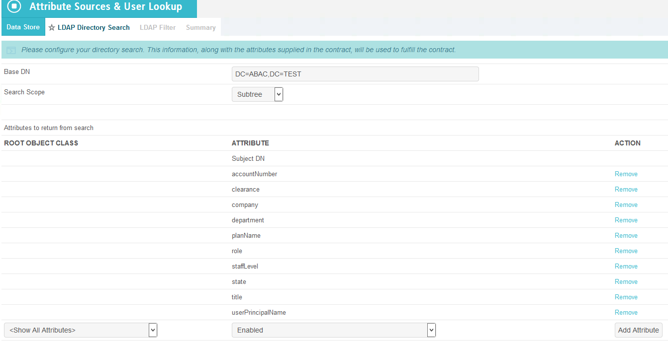
Click Next.
In the Filter field, enter sAMAccountName=${ise_user_name}.
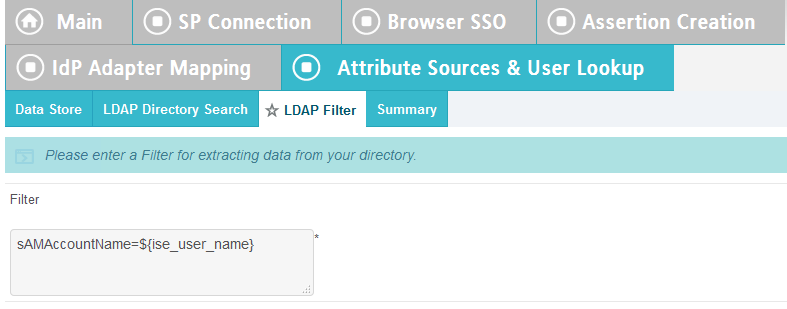
Click Next.
Click Save.
Click on Attribute Sources & Data Store.
Click on Add Attribute Source.
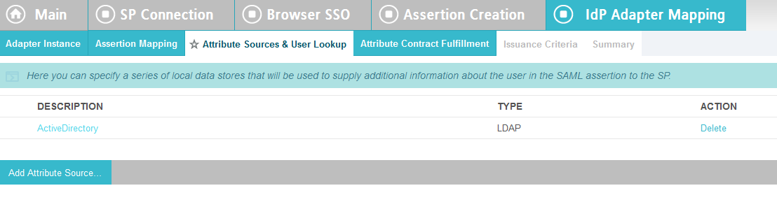
Enter RSAAA for Source Id and Description.
Select JDBC:sqlserver in the Active Data Store drop-down.

Click Next.
Select dbo in the Scheme drop-down.
Select EVENT_LOG in the Table drop-down.
Add each of the columns from the table.
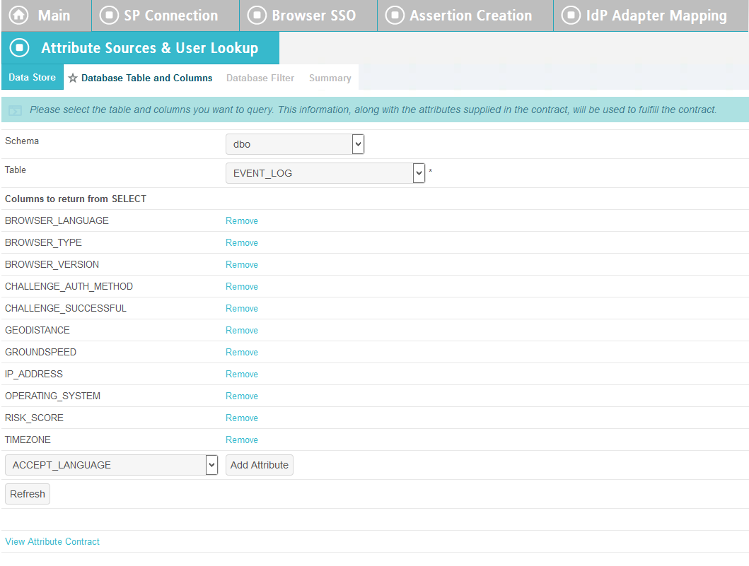
Click Next.
In the Where field, enter USER_ID=${transactionid}.
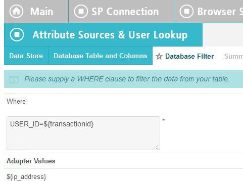
Click Next.
Click Done.
Click Next.
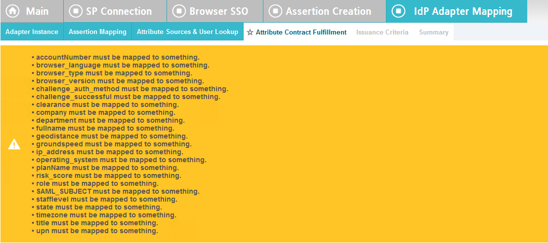
Map all the attributes as shown in the screenshot below.
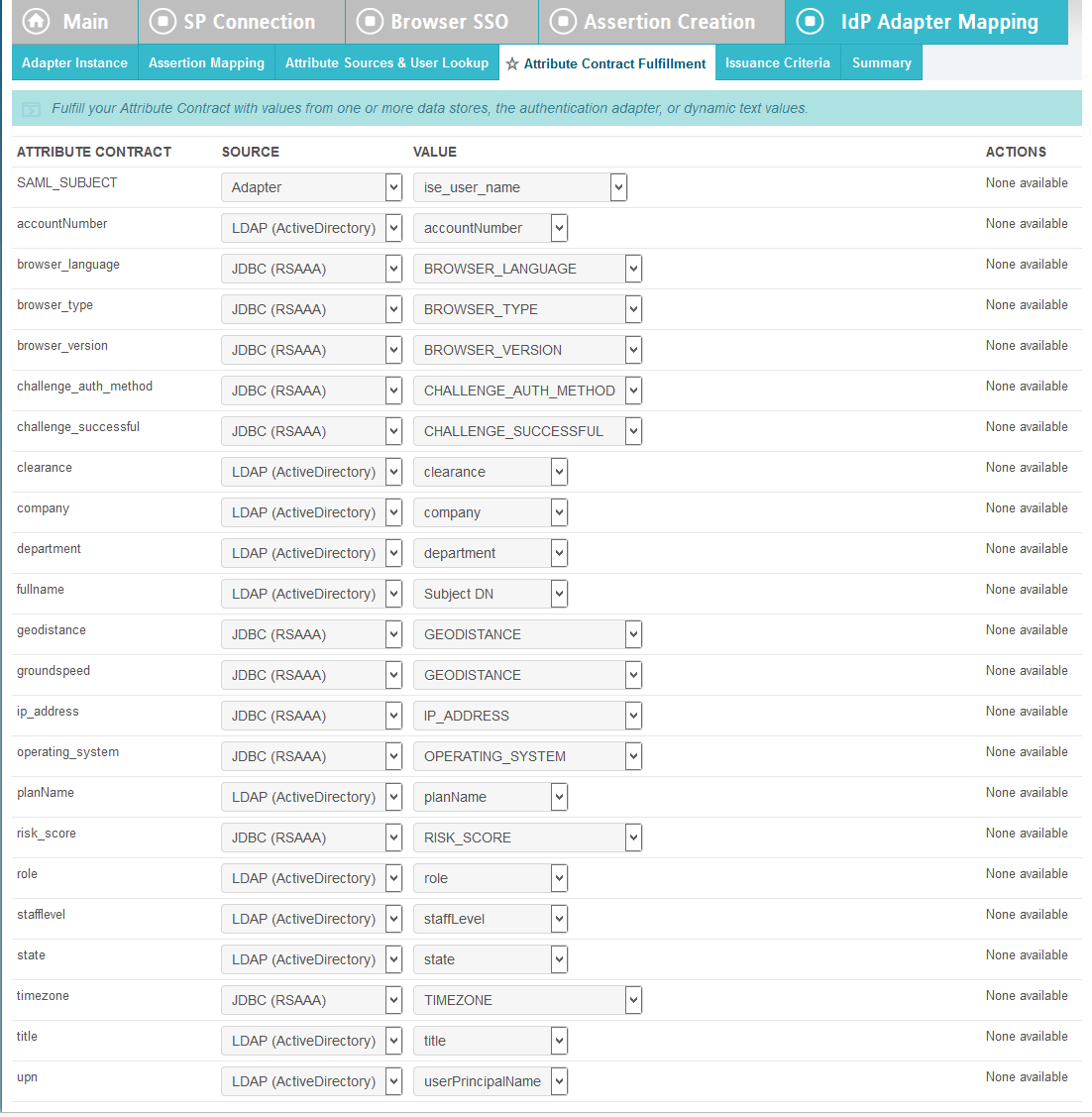
Click Next.
Click Next.
Click Save.
Back at the main page, click on rp.abac.test under SP Connections.
Scroll down and click on Database Filter.
In the Where field, enter EVENT_ID=${transactionid}.
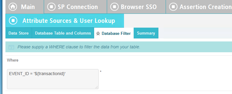
Click Save.
2.14. Certificates
Once you have installed the various products for this ABAC build, you can replace the default self-signed certificates with certificates signed by a Certificate Authority (CA). For our build, we used Symantec’s Managed PKI Service to sign our certificates using a local CA. Certificates were used to support various exchanges that require encryption, such as digital signature, SAML message encryption, and encryption of TLS communications.
Although the detailed instructions of configuring certificates signed by a CA vary by vendor product, the general process is described below. For each certificate, you perform the following high-level steps:
- Using the vendor product (e.g., PingFederate, SharePoint), generate a certificate signing request on the server where you want to use the certificate. Save the signing request to a file.
- Submit an enrollment request to your CA. You will need to provide the signing request that was generated in Step 1. This step is typically where you provide information such as the name of the server you intend to use the certificate on (e.g., “idp.abac.test”).
- A representative at the CA will examine the enrollment request and approve it. The representative will issue a certificate response signed with the CA’s key. You can download the signed response. If you are using a CA that is locally managed by your organization, you will also need to download the public key of the CA, because you will need to add this the Trusted Certificate Authorities on each server and client that will be using the certificates.
- Go back to the vendor product where you created the certificate signing request. If you are using a local CA, you will first need to add the Certificate Authority’s public key to the list of Trusted Certificate Authorities.
- Import the certificate file for your server that was signed by the CA.
2.14.1. Certificate Configuration PingFederate
In the PingFederate app, on the main menu, under Certificate Management, click Trusted CAs to import the public key of your local CA. If you are using a well-known, external, major CA and that authority’s public key is already available in cacerts in the Java runtime, it is not necessary to import the same certificate into the PingFederate Trusted CA store.
For SSL Server certificates, follow the instructions in the link below. The applicable sections are “To create a new certificate,” “To create a certificate-authority signing request,” and “To import a certificate authority response.” Once you have imported a signed certificate response, you will need to active the certificate on the PingFederate runtime server instance on which your applications are running. Follow the instructions in the section “To activate a certificate.”
For digital signatures and performing encryption / decryption, follow the instructions in the link below. The applicable sections are the same as for SSL Server certificates.
2.15. Functional Test of All Configurations for Section 2
The instructions in this section will help perform an integrated test all of the configurations in Section 2. Using the browser and PingFederate, a user will log on and validate that the federated authentication to Microsoft AD and RSA AA are properly configured.
The test for this section was performed using the Mozilla Firefox browser and the “SAML tracer” add-on, which enables examination of HTTPS POST and SAML messages.
Install the Firefox SAML tracer add-on from the link below.
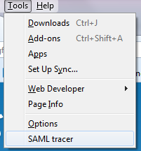
Launch your Firebox browser and select SAML tracer from the Tools menu.
This will launch an empty SAML tracer window.
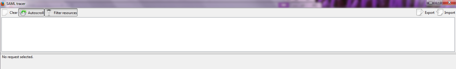
Minimize the SAML tracer window. The SAML tracer will automatically record the details of the HTTPS messages in the background.
Go back to the main browser window and navigate to the Identity Provider’s SSO Application Endpoint URL identified in the previous section (e.g., https://idp.abac.test:9031/idp/startSSO.ping?PartnerSpId=https://rp.abac.test:9031).
Expected Result: You should see the PingFederate Sign On screen.
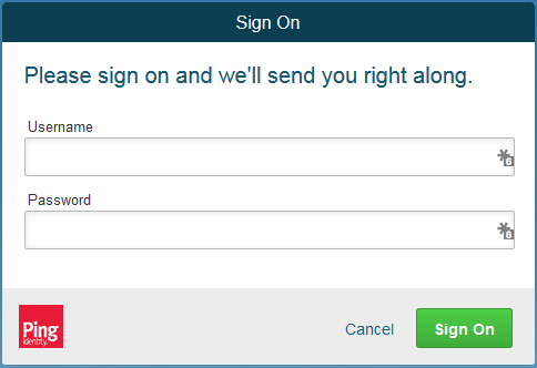
Enter the Username of the account created in Microsoft AD earlier in this section (e.g., lsmith).
Enter an invalid password for the account. Do not enter the correct password.
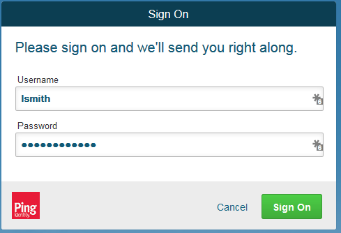
Click Sign On.
Expected Result: You should see an error message that states, “We didn’t recognize the username or password you entered.”
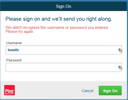
Close the existing browser and launch a new browser.
Navigate to the Identity Provider’s SSO Application Endpoint URL again.
Enter the user name of the account created earlier in this section (e.g., lsmith). Then, enter the correct password.
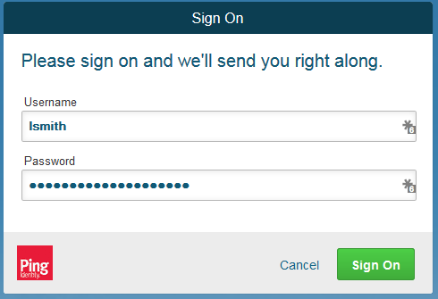
Click Sign On.
Expected Result: You should see the two-factor RSA AA plug-in screen. This screen prompts you to enter the SMS text validation code received by your mobile phone.
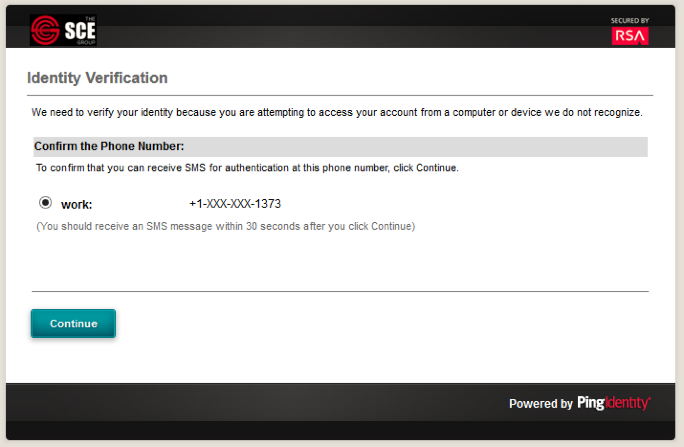

Enter the SMS validation code received on your mobile phone and proceed. This will initiate a communication with the RSA AA server to validate the code that was entered.
Expected Result: The browser should redirect to the RP’s Federation Server (e.g., rp.abac.test), and you should see an error message similar to the screenshot below.
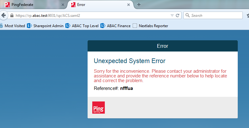
Go back to the SAML tracer window. Scroll to the bottom of the list of messages in the upper pane. Click on the last message (e.g., POST https://rp.abac.test:9031/sp/ACS.saml2) that has a SAML icon associated with it. This will show the details of the POST message.
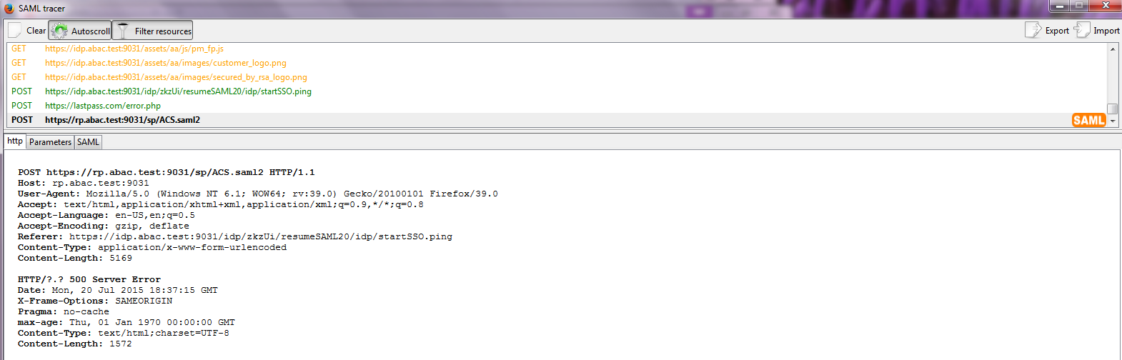
Expected Result: In the details page at the bottom, on the http tab, you should see that the browser sent a POST message to the RP’s PingFederate server rp.abac.test. The HTTP response status code (identified on the line that begins with HTTP) should be a 500 Server Error.
Click on the SAML tab.
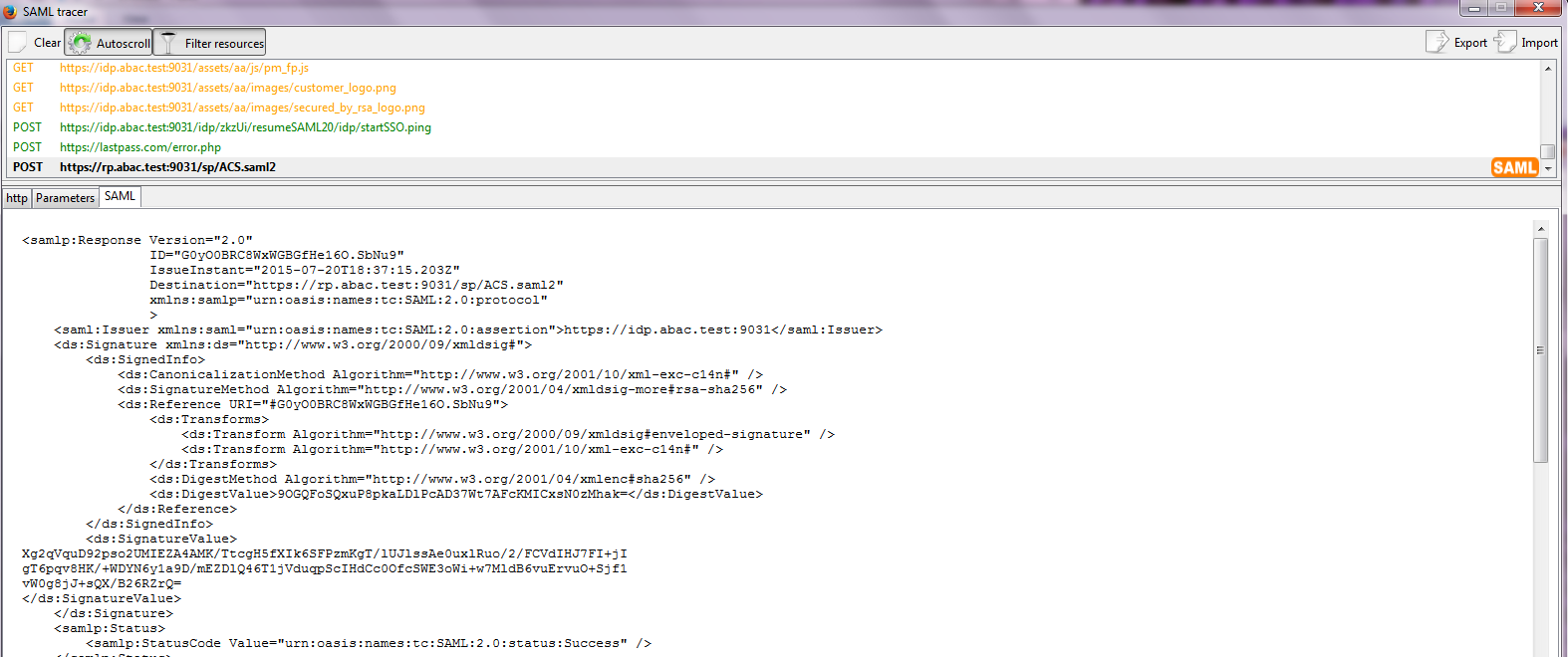
Expected Result: You should see the details of the SAML message, including the Issuer. The Issuer should be the IdP’s Federation server, idp.abac.test.
3. Setting up Federated Authentication Between the Relying Party and the Identity Provider
3.1. Introduction
In the previous section of this How-To Guide we demonstrated how to set up federated, SAML-based authentication at the identity provider (IdP). Before continuing with this section, it is necessary to have a working federation service that will represent the identity provider and can receive and issue SAML 2.0 request and responses. For instructions on how to set this up using Ping Federate, please refer to Section 2 of this guide.
In order to federate identities and attribute information between organizations a federation service must exist at both the identity provider and the relying party (RP). A trust relationship between these two services must then be instantiated to allow for identity and attribute requests and responses. In this section we configure an instance of PingFederate (henceforth called PingFederate-RP) at the relying party to act as a federation service and to redirect users to the PingFederate-IdP via a SAML request. We then configure the trust relationship and federated authentication between the PingFederate-RP and the PingFederate-IdP, allowing the SAML request to be processed by the identity provider and the subsequent return of a SAML response containing identity and attribute assertions.
If you follow the instructions in this How-To Guide section, you will be able to perform a functional test to verify the successful completion of the steps for installing, configuring, and integrating the components.
3.2. Components
Federated authentication between the relying party and the identity provider involves the following distinct components:
- PingFederate-IdP: A federation system or trust broker for the identity provider
- PingFederate-RP: Serves as the trust broker for SharePoint
3.2.1. PingFederate-IdP
Ping Identity PingFederate-IdP serves as a federation system or trust broker for the IdP. PingFederate-IdP provides initial user authentication and retrieval of user attributes to satisfy SAML requests from the RP. Once the user has been authenticated, PingFederate-IdP queries subject attributes from AD and environmental attributes from the RSA AA event log. PingFederate-IdP takes the name:value pairs of both the subject and environmental attributes and stores them in a SAML 2.0 token to be sent to the RP.
PingFederate Usage Notes:
When using the PingFederate application to perform an administrative configuration, there is usually a sequence of screens that require user entry, ending with a summary page. Once you click Done on the summary page, you must also click Save on the following page to save the configurations. If you forget to click Save, you may inadvertently lose changes to the configuration.
In the PingFederate application and associated documentation, the relying party is referred to as the “Service Provider.”
When using the PingFederate application to perform configuration, refer to the title of the tab with a small star icon to its left, to identify the item you are currently configuring. For example, if you navigated to the following screen, you would be on the IdP Adapter screen.
3.2.2. PingFederate-RP
Ping Identity PingFederate-RP serves as the trust broker for SharePoint. When the user requires authentication, PingFederate-RP redirects the user to the IdP via a SAML request to get the necessary assertions. Once authenticated, PingFederate-RP arranges for the browser’s HTTPS content to have the proper information in proper format for acceptance at the target resource (SharePoint).
3.3. Export Metadata from the Identity Provider
Follow the instructions in this section to export a metadata file from the PingFederate-IdP.
Logon to the server that hosts the PingFederate service for the Identity Provider.
Launch your browser and navigate to the PingFederate application URL: https://<DNS_NAME>:9999/pingfederate/app.
Replace DNS_NAME with the fully qualified name of the Identity Provider’s PingFederate server (e.g., https://idp.abac.test:9999/pingfederate/app). Logon to the PingFederate application using the credentials you configured during installation.
On the Main Menu under Administrative Functions, click Metadata Export.
On the Metadata Mode screen, select Use a connection for metadata generation.
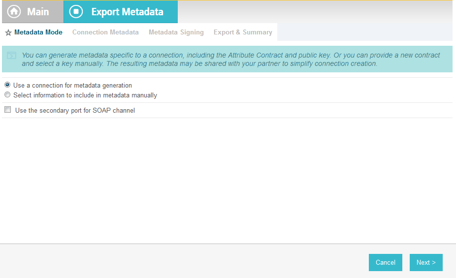
Click Next. On the Connection Metadata screen, select the connection to the relying party that you configured in the previous section (e.g., https://rp.abac.test:9031). This should automatically populate some of the fields on the screen with information from the connection.
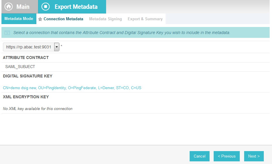
Click Next. On the Metadata Signing screen, if you plan to sign the metadata file that will be exported, select the certificate that will be use to sign the file.
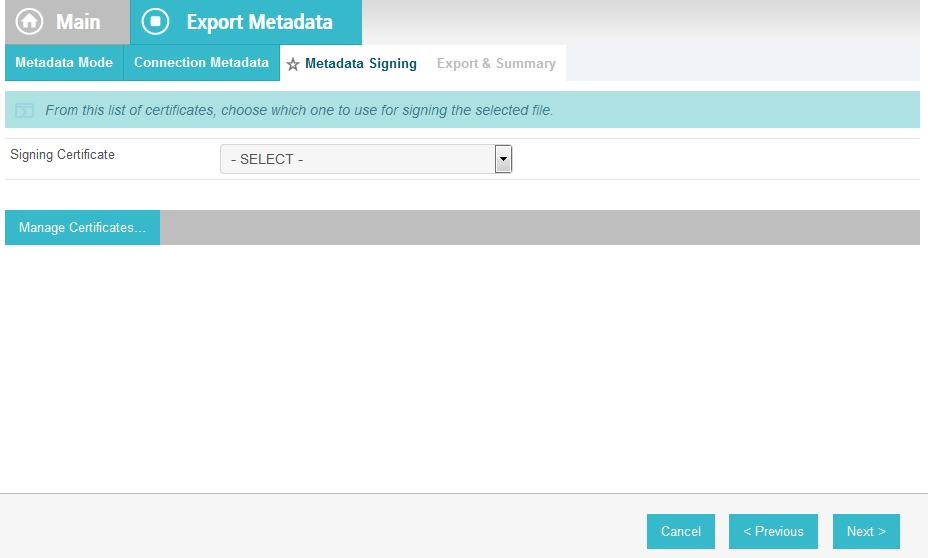
Click Next. On the Export & Summary screen, you should see a summary of the options that were selected.
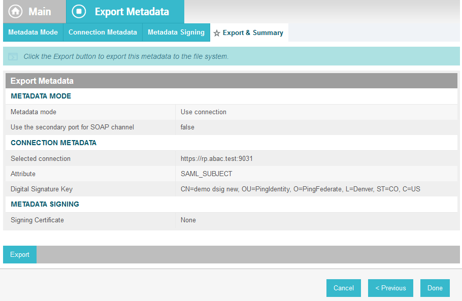
Click Export. This will create an export file that contains the metadata of the identity provider that you can download using the browser.
Copy the metatdata file to the server that hosts the PingFederate service for the relying party.
3.4. Configure PingFederate-RP Connection to the PingFederate-IdP
Follow the instructions in this section to configure a PingFederate connection from the relying party to the identity provider.
Logon to the server that hosts the PingFederate service for the relying party.
Launch your browser and go to: https://<DNS_NAME>:9999/pingfederate/app.
Replace DNS_NAME with the fully qualified name of the relying party’s PingFederate server (e.g., https://rp.abac.test:9999/pingfederate/app). Logon to the PingFederate application using the credentials you configured in the previous installation section.
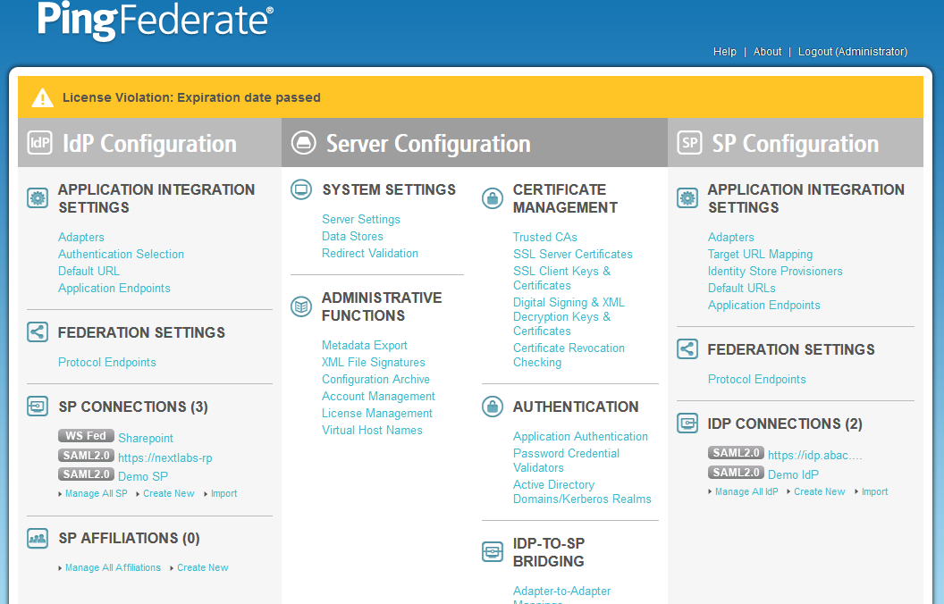
On the Main Menu under IDP CONNECTIONS, click Create New.
On the Connection Type screen, select Browser SSO Profiles.

Click Next.
On the Connection Options screen, make sure Browser SSO is selected.
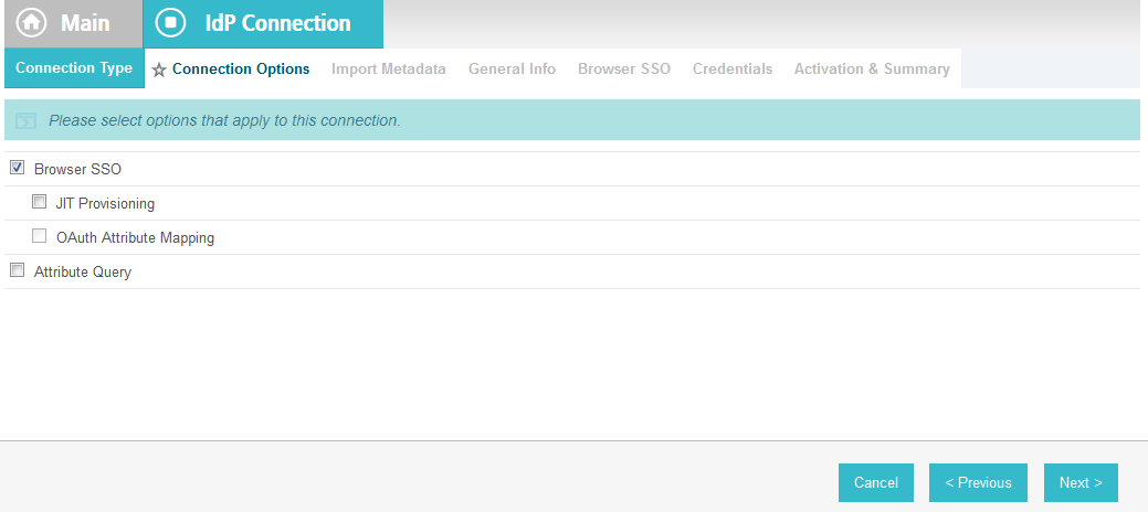
Click Next.
On the Import Metadata screen, click Browse and select the metadata file that you exported from the Identity Provider’s PingFederate server.
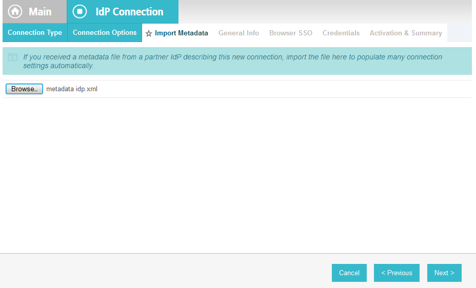
Click Next.
On the Metadata Summary screen, click Next. On the General Info screen, you should see some configuration information (e.g., Base URL) about the identity provider that was taken from the metadata file that you selected.
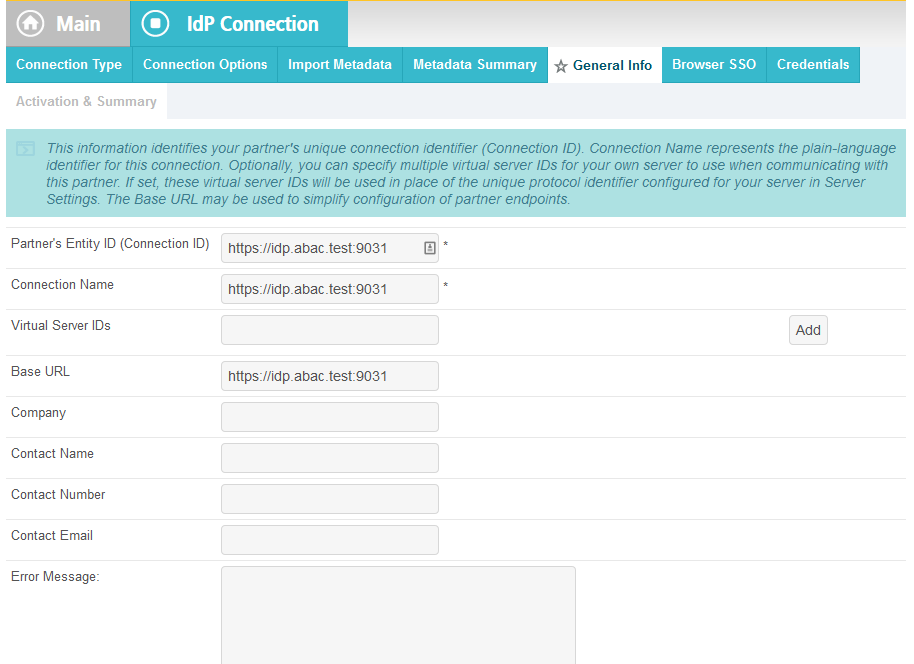
Click Next.
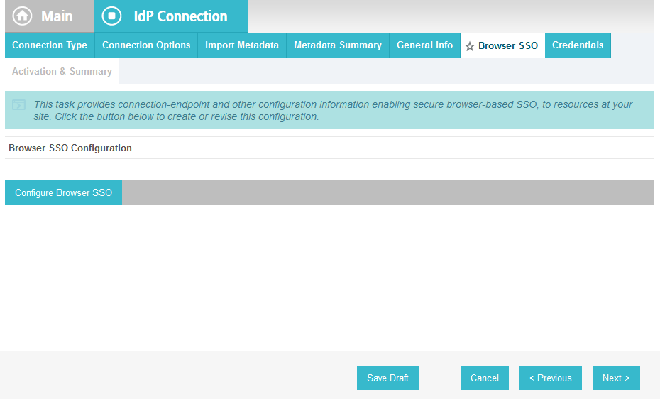
On the Browser SSO screen, click Configure Browser SSO.
On the SAML Profiles screen, select IdP-Initiated SSO and SP-Initiated SSO.
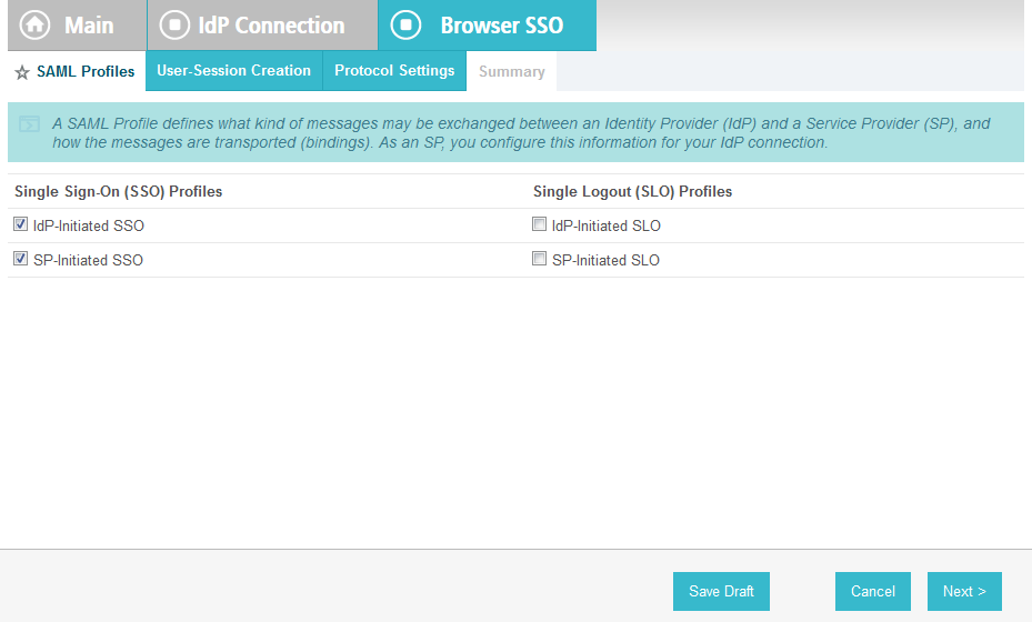
Click Next.
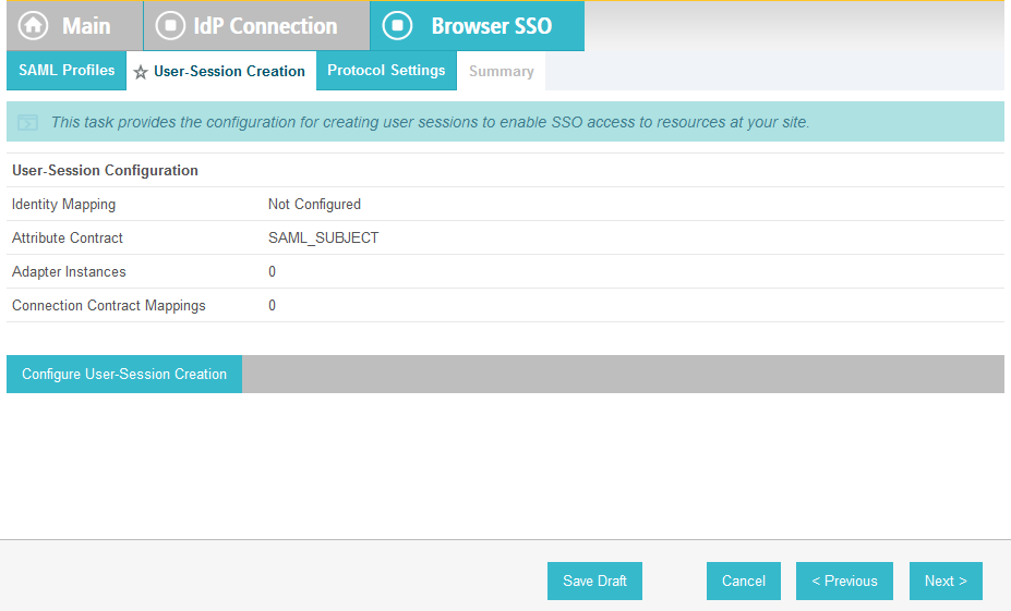
On the User-Session Creation screen, click Configure User-Session Creation.
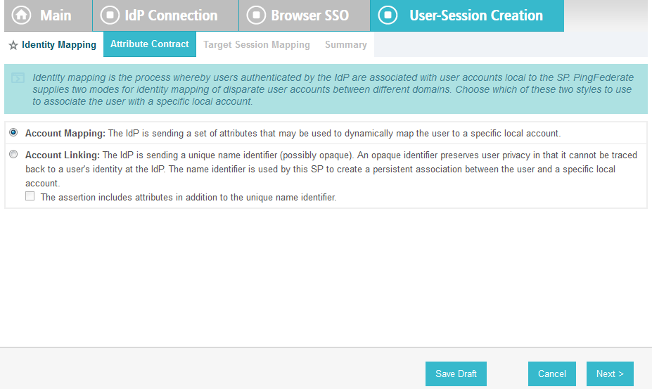
On the Identity Mapping screen, click Next.
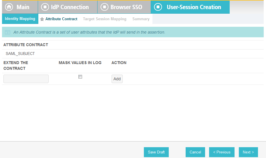
On the Attribute Contract screen, click Next.
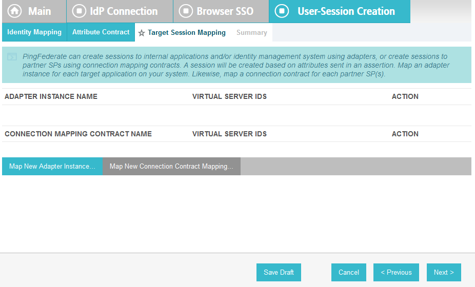
On the Target Session Mapping screen, click Map New Connection Contract Mapping.
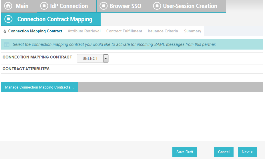
On the Connection Mapping Contract screen, click Manage Connection Mapping Contracts.
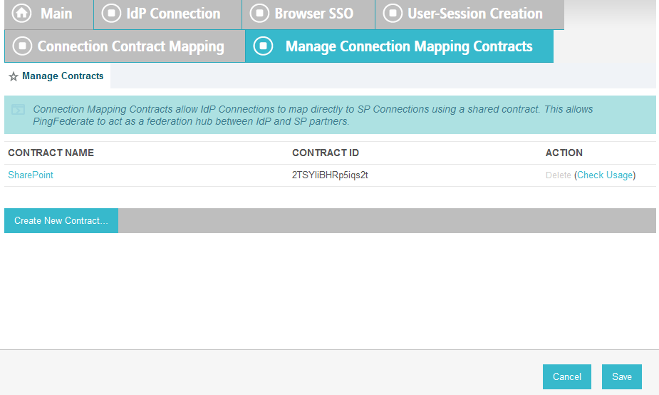
On the Manage Contracts screen, click Create New Contract.
On the Contract Info screen, enter the Contract Name (e.g., SharePoint 2013).
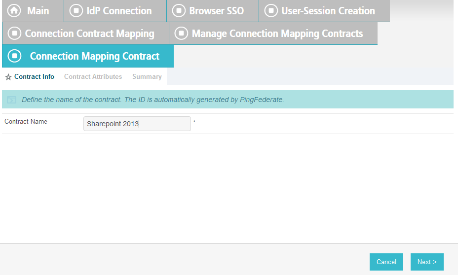
Click Next.

Click Next.
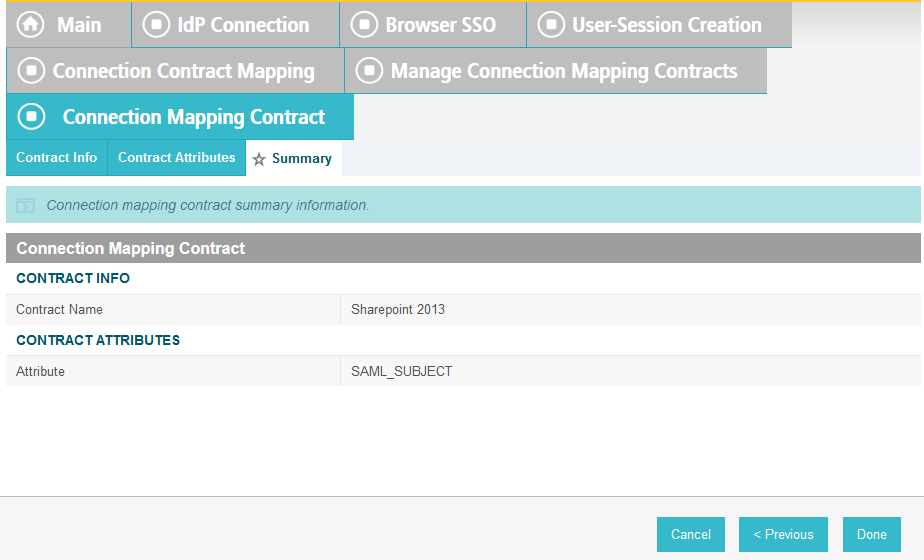
On the Summary screen, click Done.
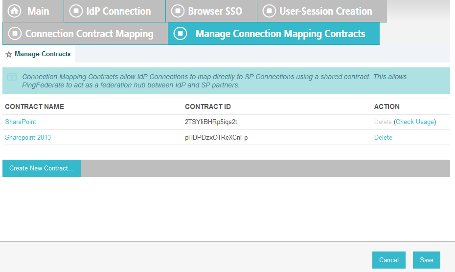
On the Manage Contracts screen, you should see the new contract listed. Click Save.
On the Connection Mapping Contract screen, for the CONNECTION MAPPING CONTRACT field select the name of the new contract that was created (e.g., SharePoint 2013).
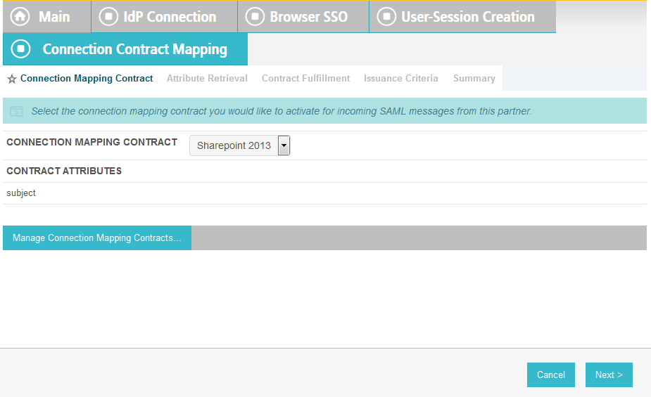
Click Next. On the Attribute Retrieval screen, select Use only the attributes available in the SSO Assertion.
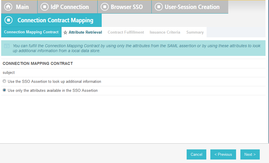
Click Next. On the Contract Fulfillment screen, for the SOURCE field select Assertion. For the VALUE field, select SAML_SUBJECT.
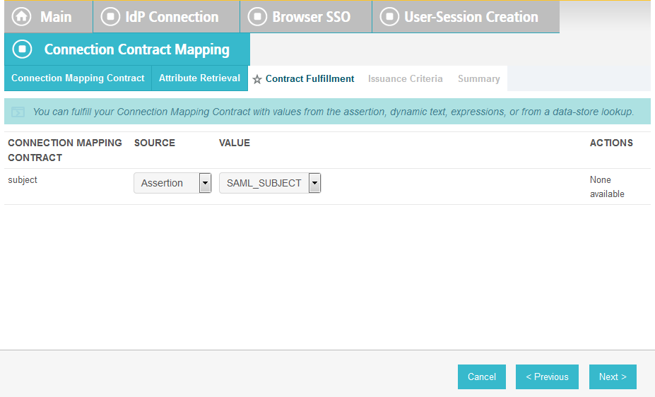
Click Next.
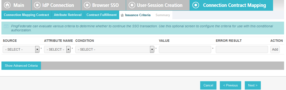
On the Issuance Criteria screen, click Next.
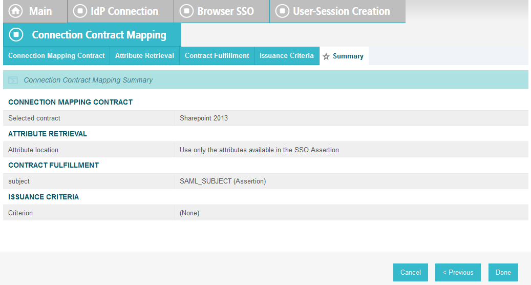
On the Summary screen, click Done.
On the Target Session Mapping screen, you should see new contract (e.g., SharePoint 2013) listed under the CONNECTION MAPPING CONTRACT NAME field.
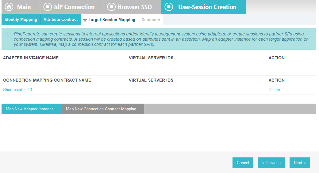
Click Next.
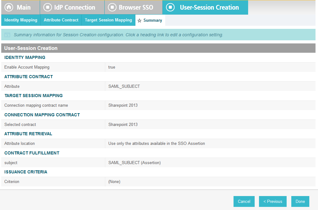
Click Done.
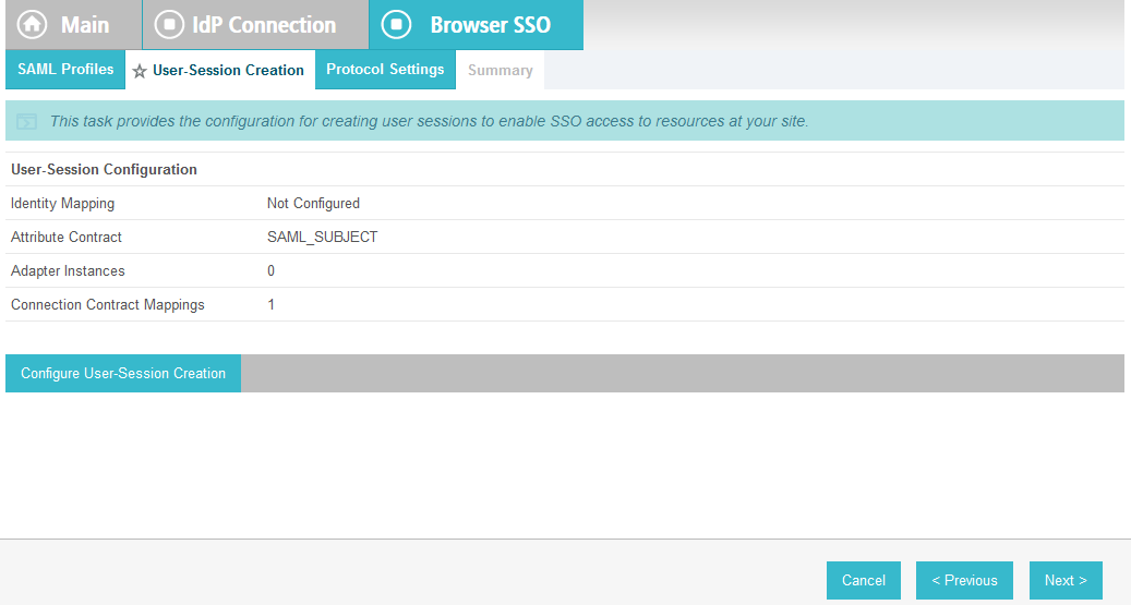
On the User-Session Creation screen, click Next.
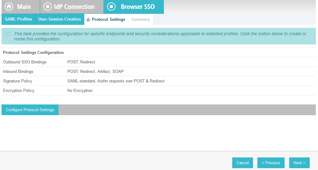
On the Protocol Settings screen, click Configure Protocol Settings. This will bring up a sequence of sub-screens.
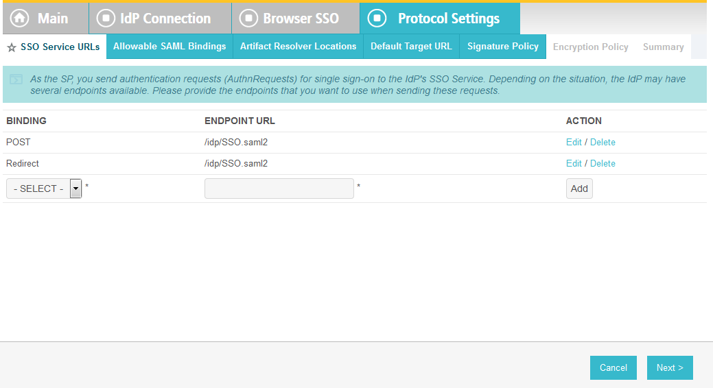
On the SSO Service URLs screen, click Next.
On the Allowable SAML Bindings screen, select POST and select Redirect.
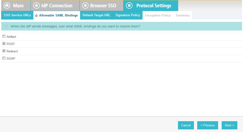
Click Next.
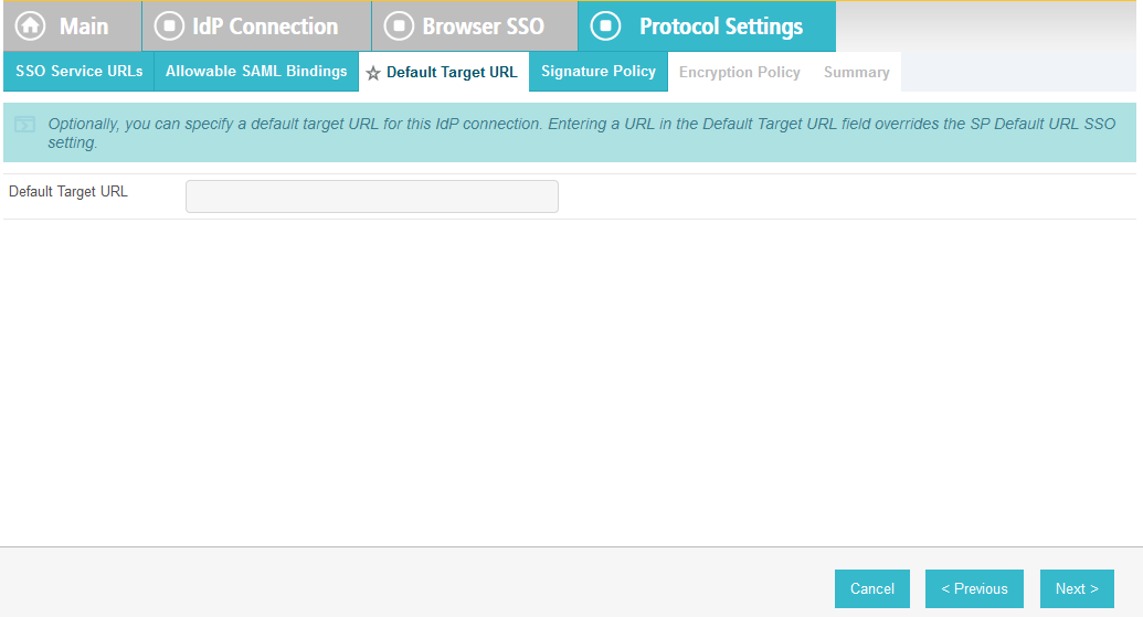
On the Default Target URL screen, click Next.
On the Signature Policy screen, make sure that the following are selected:
- Specify additional signature requirements and
- Sign AuthN requests sent over POST and Redirect bindings
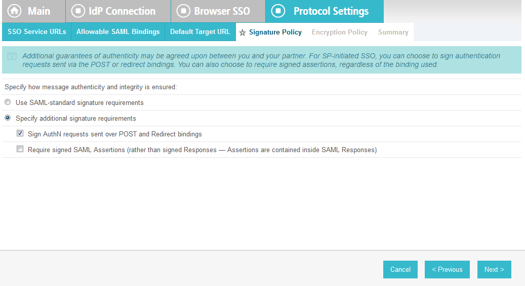
Click Next. On the Encryption Policy screen, select
- Allow encrypted SAML Assertions and SLO messages and
- The entire assertion
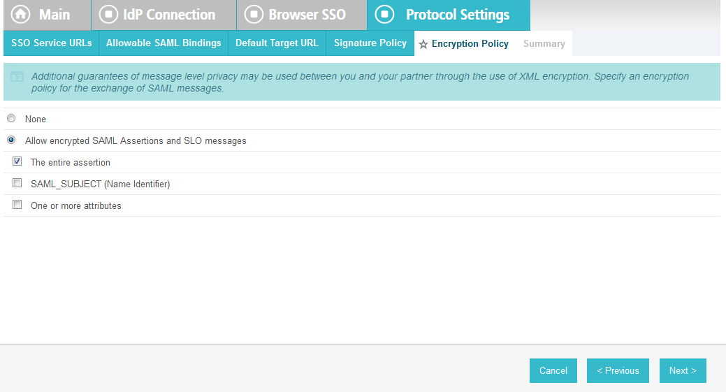
Click Next.
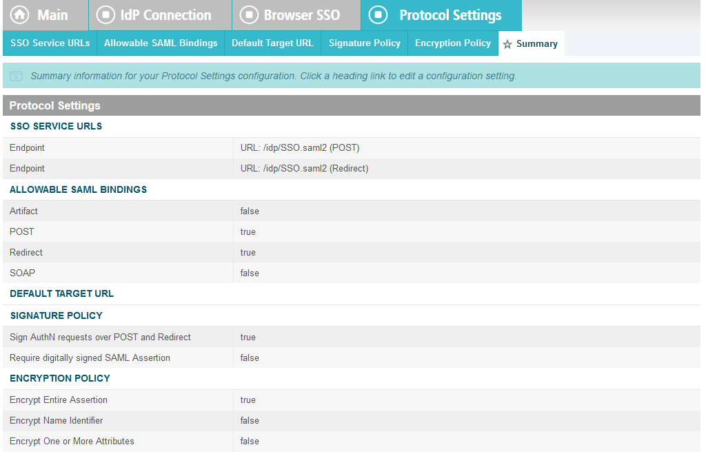
On the Summary screen, click Done.
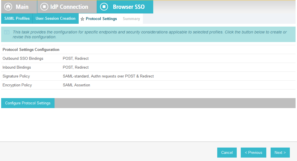
On the Protocol Settings screen, click Next.
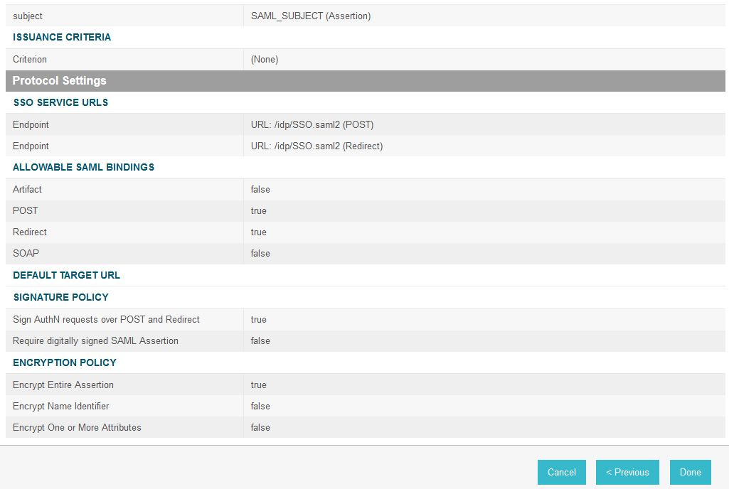
On the Summary screen, click Done.

On the Browser SSO screen, click Next.
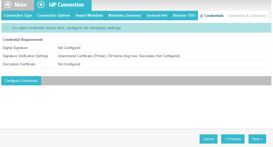
On the Credentials screen, click Configure Credentials.
On the Digital Signature Settings screen, select
- Signing Certificate for SAML messages and
- Signing Algorithm
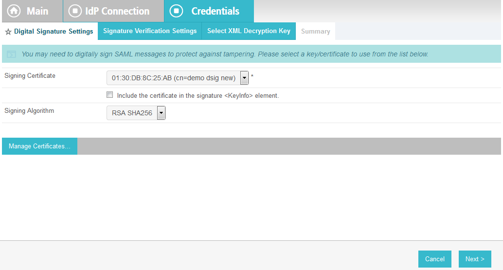
Click Next.
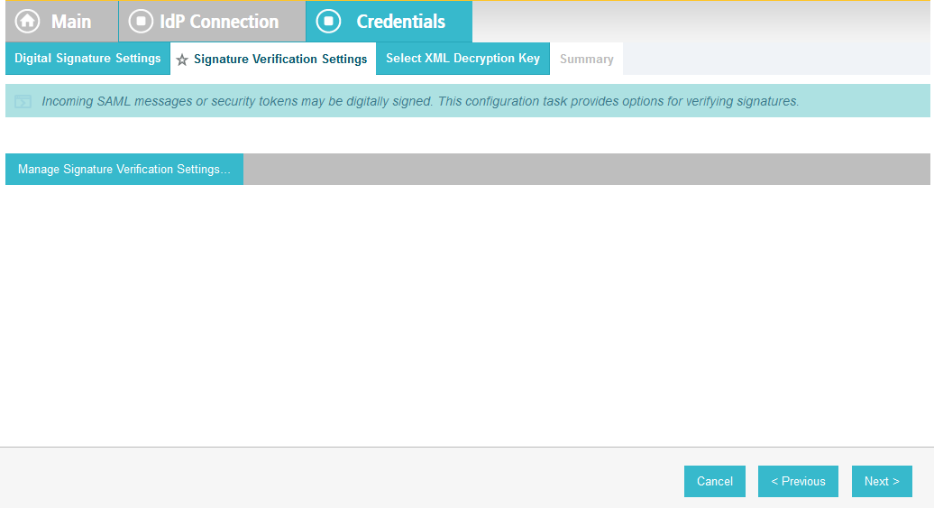
On the Signature Verification Settings screen, click Manage Signature Verification Settings.
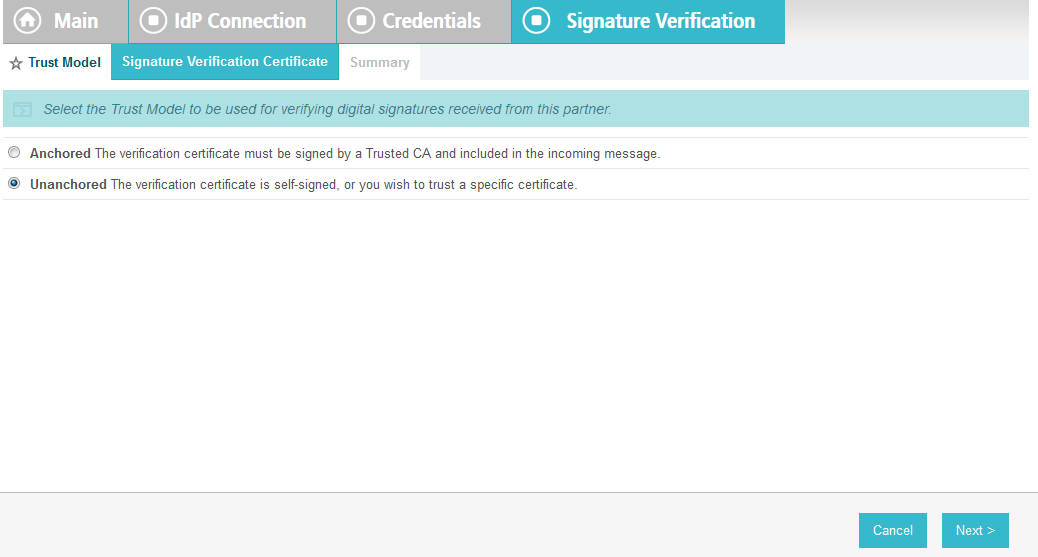
On the Trust Model screen, click Next.
On the Signature Verification Certificate screen, select the certificate to verify digital signatures.
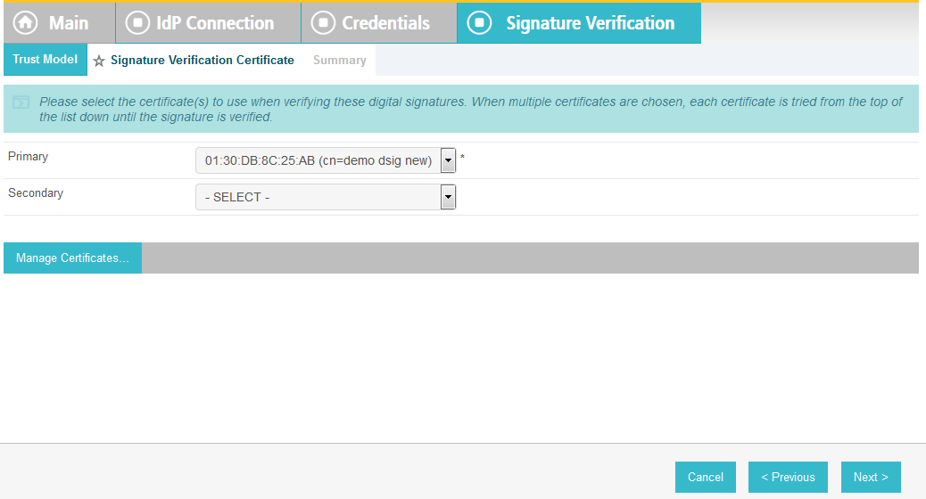
Click Next.
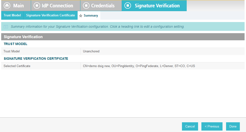
On the Summary screen, click Done.
On the Signature Verification Settings screen, click Next.
On the Select XML Decryption Key screen, select the certificate associated with the private key that will decrypt messages from the identity provider.
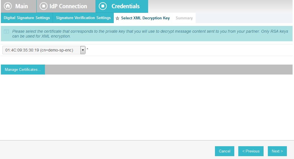
Click Next.
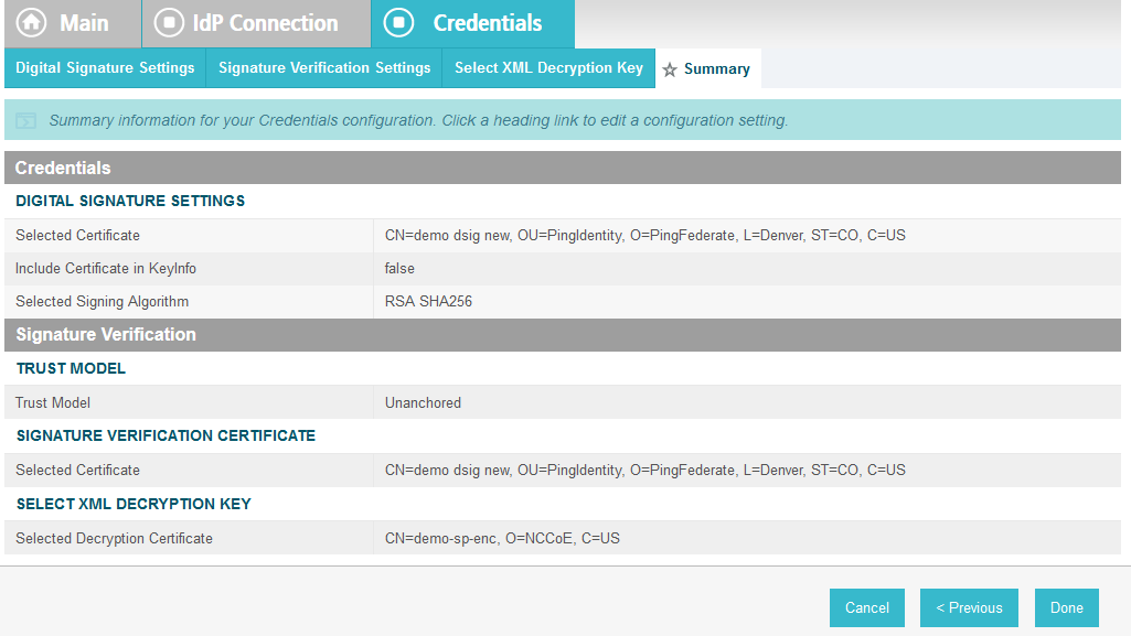
On the Summary screen, click Done.

On the Credentials screen, click Next.
On the Activation and Summary screen, select Active for the
Connection Status field.
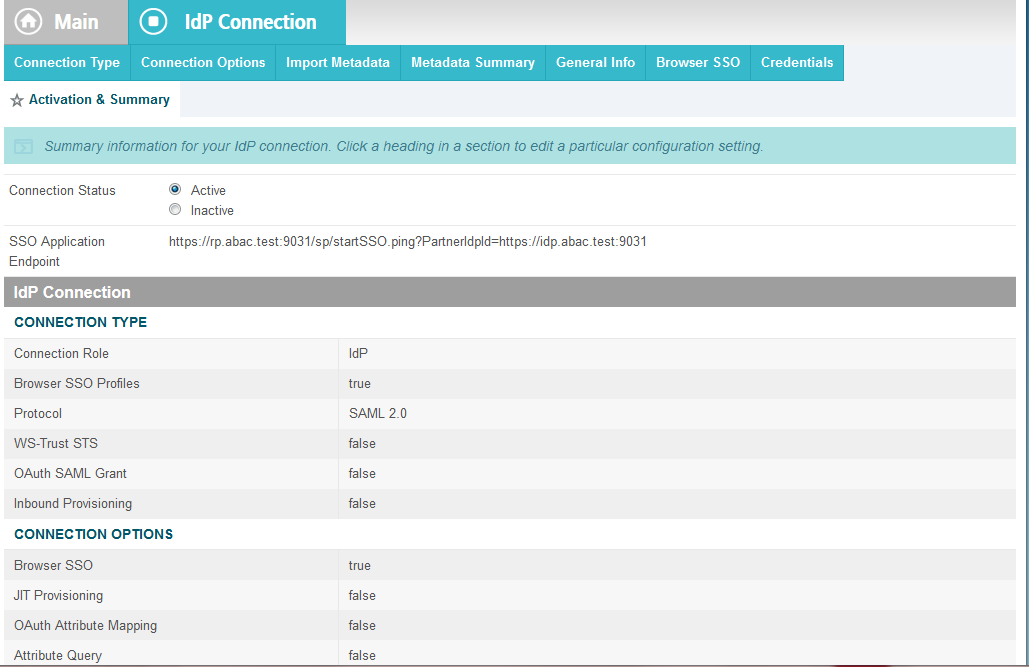
- Copy the relying party’s SSO Application Endpoint URL (e.g., https://rp.abac.test:9031/sp/startSSO.ping?PartnerIdpId=https://idp.abac.test:9031) to the clipboard and save it to a text file, because this URL will be used in the Functional Test section.
- Click Save to save the configuration.
3.5. Functional Test of All Configurations for Section 3
This section provides instructions to perform an integrated test all of the configurations in Section 3.
Using the browser and PingFederate, a user will logon at the identity provider, and then get redirected to the relying party.
Note: This test is similar to the test in Section 2, except this time the relying party has a destination endpoint connection that was configured in Section 3, so the response code from the relying party’s Federation server (e.g., rp.abac.test), should be an HTTP 200 status code.
Launch your browser and navigate to the relying party’s SSO Application Endpoint URL identified in the previous section (e.g., https://rp.abac.test:9031/sp/startSSO.ping?PartnerIdpId=https://idp.abac.test:9031).
Launch the SAML tracer as in Section 2 and minimize the tracer window.
Expected Result: You should see the PingFederate Sign On screen.
Enter the Username and Password of the account created in Section 2 (e.g., “lsmith”) and click Sign On.
When the RSA Adaptive Authentication screen comes up, enter the SMS text validation code.
Expected Result: You should see the browser redirect to the relying party’s Federation Server (e.g., rp.abac.test) and an error message similar to the message in the following screenshot.
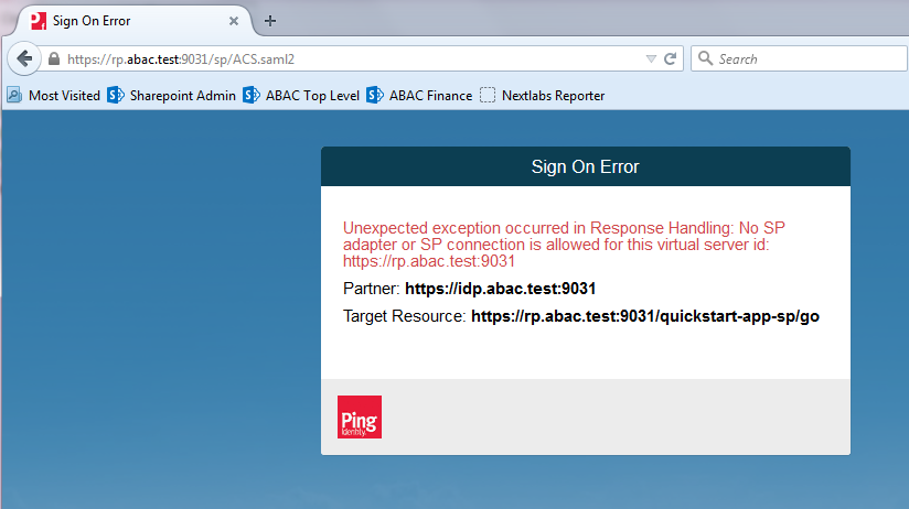
Return to the SAML tracer window.
Scroll to the bottom of the list of message in the upper pane.
Click on the last message (e.g., POST https://rp.abac.test:9031/sp/ACS.saml2) that has a SAML icon associated with it. This will show the details of the POST message.
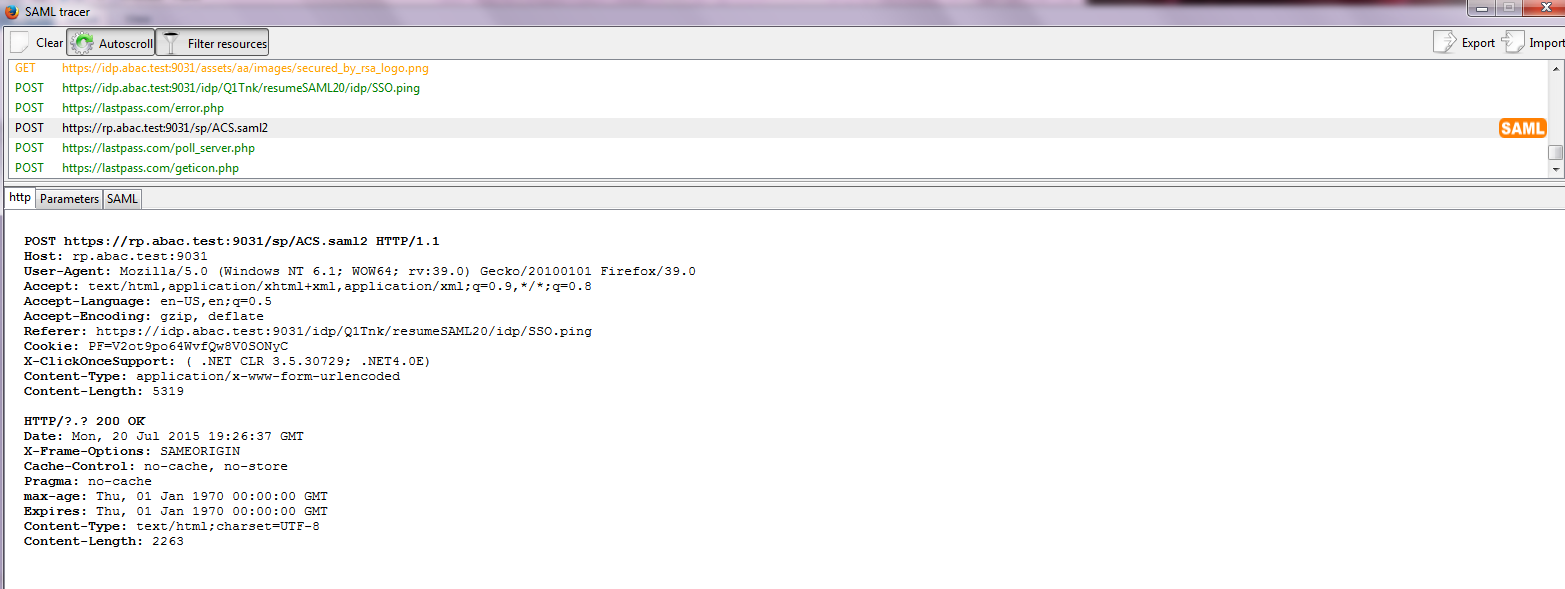
Expected Result: In the details page at the bottom, on the http tab, you should see that the browser sent a POST message to the relying party’s PingFederate server (e.g., rp.abac.test). The HTTP response status code (identified on the line that begins with “HTTP”) should be a 200 OK code.
4. Installing and Configuring Microsoft SharePoint Server and Related Components
4.1. Introduction
In previous sections of this How-To Guide, we installed several products to establish RP and IdP environments, their components, and the federation between them (Section 2 and Section 3).
In this section of the How-To Guide we will illustrate how to install IIS (Internet Information Services 8), Microsoft SQL Server 2012, and Microsoft SharePoint Server 2013. Then, within SharePoint we will illustrate how to create a web application, configure the web application to run SSL, create a site collection, and create sub-sites.
In our build, we used ABAC policies and policy enforcement to protect RP resources like SharePoint sites and documents with the help of NextLabs products installed in subsequent How-To sections (Section 7 and Section 8).
4.1.1. Components Used in this How-To Guide
- Internet Information Services (IIS) Manager - extensible web server created by Microsoft (formerly Internet Information Server) and is pre-installed in most Windows editions though is not active by default.
- Microsoft SharePoint 2013 - Microsoft SharePoint is a web-based application within the Windows operating environment. Commonly, SharePoint is deployed as a document management system for intranet, extranet, or cloud repository purposes. SharePoint natively uses an RBAC authorization environment, but it also supports the use of attributes within the user transaction request, a capability Microsoft refers to as being “claims aware.” SharePoint also allows for tagging data within its repository, which can be leveraged as object attributes.
Microsoft SQL Server 2012 - relational database management system developed by Microsoft. As a database server, it is a software product with the primary function of storing and retrieving data.
4.1.2. Required or Recommended Files, Hardware, and Software
| Component | Required Files | Required Other Software | Minimum Hardware Requirements | Recommended Hardware | Recommended or Minimum Operating System | Operating System or Other Software Used in this Build |
|---|---|---|---|---|---|---|
| Internet Information Services (IIS) 8 | Built-in component in Windows Server 2012 operating system (inactive by default) – Windows Server 2012 ISO | N/A | For the Windows 2012 Server OS: 512 MB RAM, 1.4 GHz 64-bit CPU, 32 GB hard disk; Gigabit Ethernet adapter | For the Windows 2012 Server OS: 800+ MB RAM, >1.4 GHz 64-bit CPU, >32 GB hard disk | Windows Server 2012 R2 Standard 64-bit | Windows Server 2012 R2 Standard 64-bit |
| Microsoft SharePoint Server 2013 | SharePoint Server 2013 installation setup file or DVD | Microsoft SQL Server 2012; Microsoft SQL Server Management Studio; IIS 7.0 or 8.0 (Web Server Role, 8.0 required for Windows Server 2012) | 12 GB RAM, 4 core, 64 bit CPU, 80 GB hard disk space for system drive | 8+ GB RAM, 4+core 64-bit CPU, >80 GB hard disk | The 64-bit edition of Windows Server 2008 R2 Service Pack 1 (SP1) Standard, Enterprise, or Datacenter or the 64-bit edition of Windows Server 2012 Standard or Datacenter | Windows Server 2012 R2 Standard 64-bit |
| Microsoft SQL Server 2012 | SQL Server 2012 setup file or DVD | .NET 4.0 Framework (SQL Server installs .NET 4.0 during the feature installation step.) | 1GB RAM, 1.4GHz CPU, 6 GB of hard-disk space | 4 GB RAM (should be increased as database size increases to ensure optimal performance), >2.0 GHz CPU, 6 GH of hard-disk space | Windows Server 2008 R2 or Windows Server 2012, Windows 8.1, Windows 8, Windows 7 SP1, Windows Vista SP2 | Windows Server 2012 R2 Standard 64-bit |
4.2. Installation of Required Components
4.2.1. Installing SQL Server 2012
On the server where SQL Server 2012 is going to be installed, follow the steps from this link to install SQL Server 2012: https://technet.microsoft.com/en-us/library/ms143219(v=sql.110).aspx
Note: in our build, this SQL Server instance is leveraged by SharePoint Server 2013 and by the NextLabs ABAC policy definition, deployment, and enforcement components. Two of these NextLabs components are also installed on the same server as SQL Server 2012 (Section 7). In our build, we call this server SQLServer.
It is generally recommended by Microsoft regarding SharePoint Server and NextLabs regarding Control Center that the SQL Server be installed on a separate, dedicated server, which is why we chose that deployment in our build.
4.3. Creating the Web Application (IIS site) in SharePoint
On the SharePoint Server, open a web browser.
In the URL address bar of the browser, enter the address for Central Administration and click Enter or Go: http://sharepoint:44444/default.aspx
From the Central Administration page, click on Application Management.
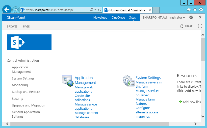
On the Application Management Page, under the Web Applications section, click on Manage web applications.
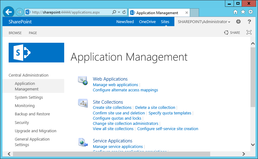
From the left-most end of the Web Applications ribbon menu click on New.
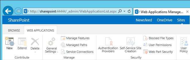
In the Create New Web Application window that automatically opens, in the IIS Web Site section, do the following steps to choose the web application’s basic IIS configuration:
Leave the radio button for Create a new IIS web site chosen (default).
Leave the default Name or change the Name to something more memorable to you.
Leave the default Port displayed or change the Port number to one that makes sense for your environment.
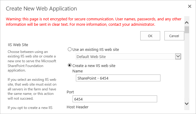
Leave the Host Header blank and keep the default Path.
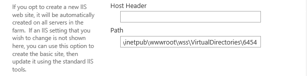
Further down in the Create New Web Application window, in the Security Configuration section, do the following steps to configure the web application to run SSL:
Under Allow Anonymous leave the No radio button chosen (default).
Under Use Secure Sockets Layer (SSL), click Yes.
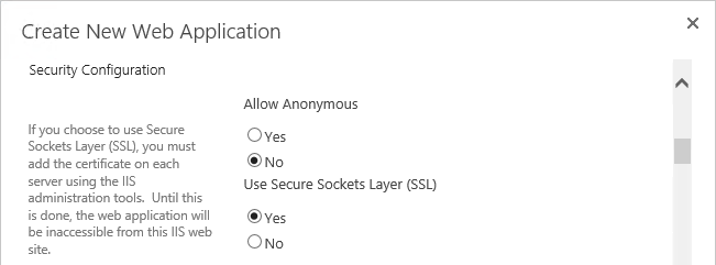
Further down in the Create New Web Application window, in the Claims Authentication Types section, do the following steps to enable Windows Authentication (as illustrated):
Click on Enable Windows Authentication
Click on Integrated Windows authentication
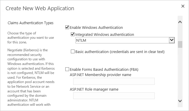
Further down in the Create New Web Application window, in the Claims Authentication Types section, note that there is a Trusted Identity provider section. Do not select this option now, but later in our build and in other How-To guide sections there will be steps for setting up the federated logon.
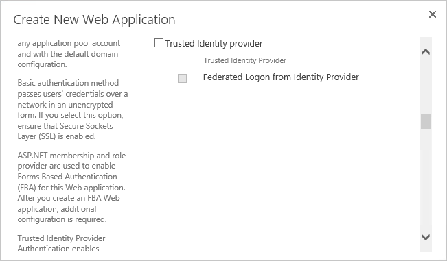
Further down in the Create New Web Application window, in the Sign In Page URL section, leave the Default Sign In Page radio button chosen (default).
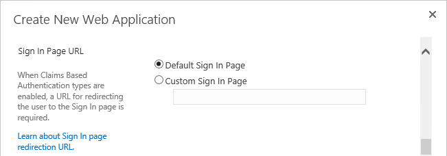
Further down in the Create New Web Application window, in the Public URL section, change the URL or keep the default URL:
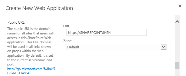
Further down in the Create New Web Application window, in the Application Pool section, leave the default values:
Leave the radio button for Create new application pool chosen.
Note that the Configurable button is already chosen to select an existing security account for the new application pool, an account called SharePointAdmin in this build
- If you do not already have a managed account for this purpose, click on the Register new managed account link and follow the prompts to create one.
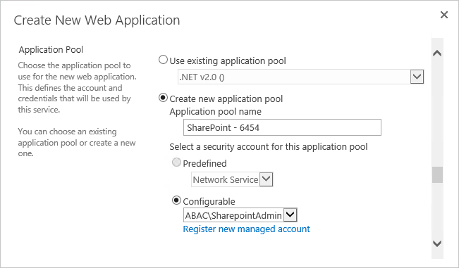
Further down in the Create New Web Application window, in the Database Name and Authentication section, leave the following fields filled in with the default information or enter your own manually:
IP Address of the Database Server. In our build the separate, dedicated SQL Server IP address is 10.33.7.210
Database name
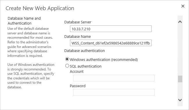
Further down in the Create New Web Application window, in the Failover Server section, leave the Failover Database Server field blank.
Further down in the Create New Web Application window, in Service Application Connections, leave the default checkbox for User Profile Service Application checked.
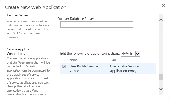
Further down in the Create New Application window, in Customer Experience Improvement Program, either keep the Enable Customer Experience Improvement Program radio button for No chosen, or click on Yes.
At the bottom of the Create New Application window click OK to finish the web application creation process.
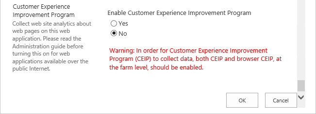
Wait for the new web application to be created.
In the Application Created window, click OK.
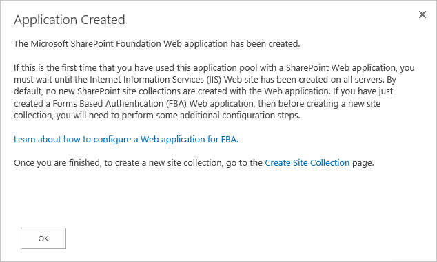
Back on the Web Applications page, verify that your new SharePoint web application is listed (“SharePoint – 6454” from this example).
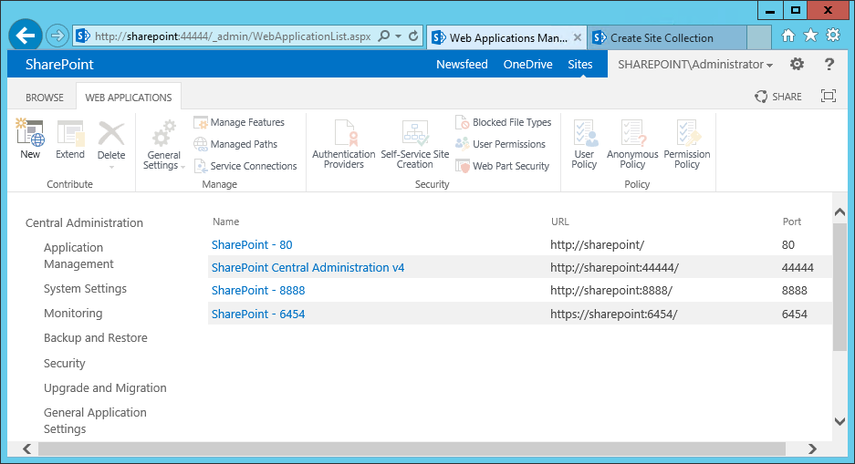
In another browser window, navigate to your new web application (e.g., https://sharepoint:6454). Until the SSL certificate is installed as seen in the following section, you will receive this error.
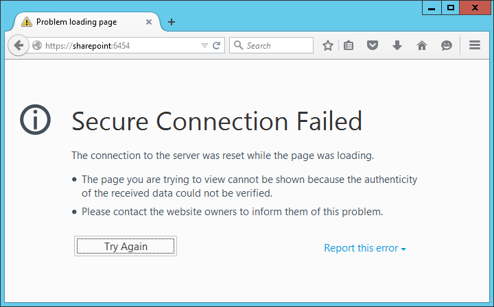
4.4. Creating and Installing SSL Certificate
For a protected lab environment, it is possible to use self-signed certificates, however for production network deployments it is generally recommended to use certificates signed by a Certificate Authority. Instructions related to both approaches are included in this section.
4.4.1. Self-Signed Certificates
4.4.1.1. Creating a Self-Signed Certificate on IIS 8
On the SharePoint Server, click on the Windows icon in the bottom left corner of your screen.
Begin typing IIS.
When the Internet Information Services (IIS) Manager appears, click on it.

Click on the SharePoint Instance to see its Features.
Scroll down and double-click on Server Certificates.
In the Server Certificates window, you will see any certificates that already exist.
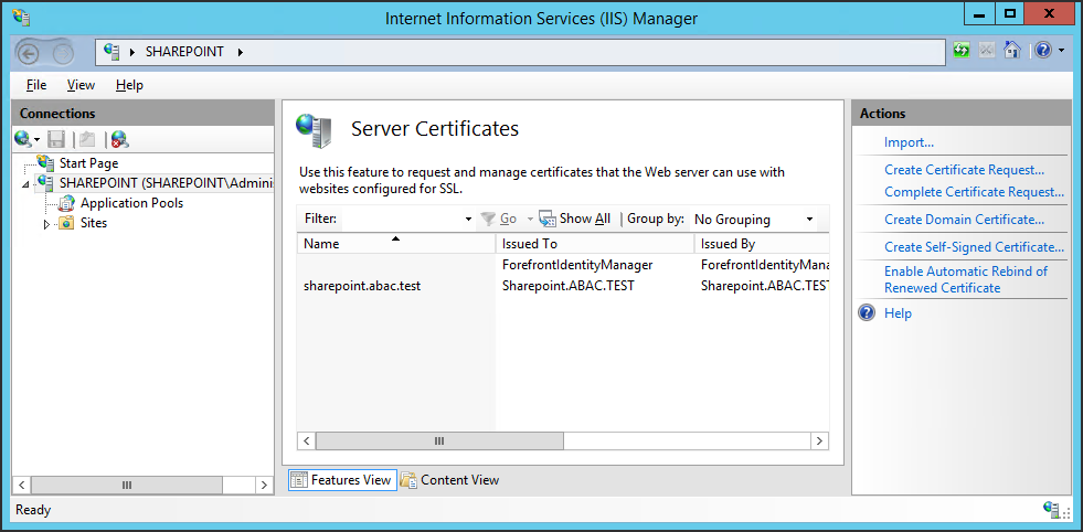
In the Actions panel on the right side of the IIS Manager window, next to the Server Certificates window, click on Create Self-Signed Certificate.
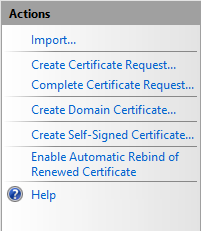
In the Create Self-Signed Certificate window, Specify a friendly name for the certificate and Select a certificate store for the new certificate, then click OK.
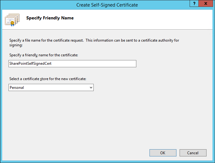
4.4.1.2. Importing Self-Signed Certificate to SharePoint Certificate Store
After creating the self-signed certificate and clicking OK in the previous sub-section, you will see your new certificate.
Double-click on the new certificate.
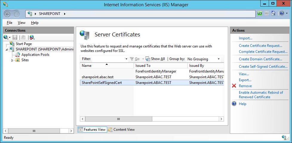
In the Details tab of the Certificate window, click on Copy to File.
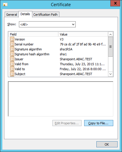
In the Certificate Export Wizard window that opens, click Next.
In the Certificate Export Wizard window on the Export Private Key screen, keep the selection No, do not export the private key and click Next.
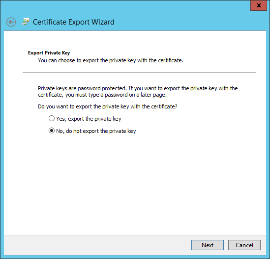
In the Certificate Export Wizard window on the Export File Format screen, select the format you want to use (DER in this example), then click Next.
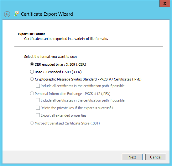
In the Certificate Export Wizard window on the File to Export screen, type in the certificate file name and click Next.
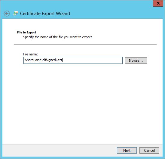
In the Certificate Export Window on the Completing the Certificate Export Wizard screen, click Finish.
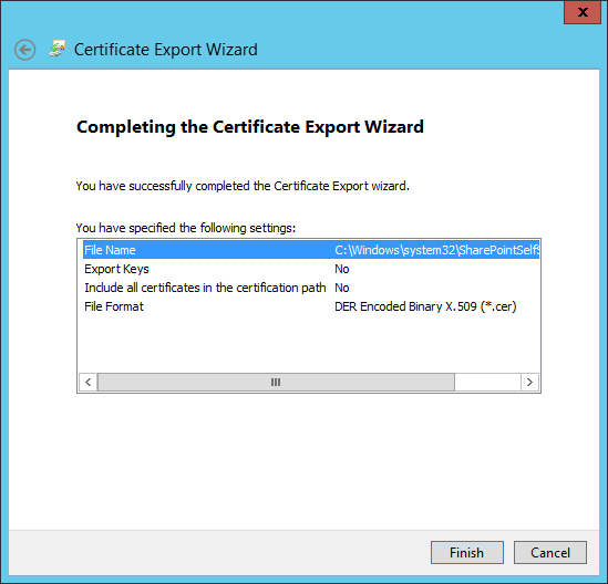
In another Certificate Export Wizard window that automatically opens, you will see that the export was successful. Click OK.
4.4.1.3. Add the Self Signed Certificate to Trust management in Central Administration
Click on the Windows icon at the bottom left corner of your screen.
Begin typing the words: manage computer certificates.
Click on the Manage Computer Certificates icon.
In the certlm window, right-click on the SharePoint node, hover over All Tasks, then click Import.
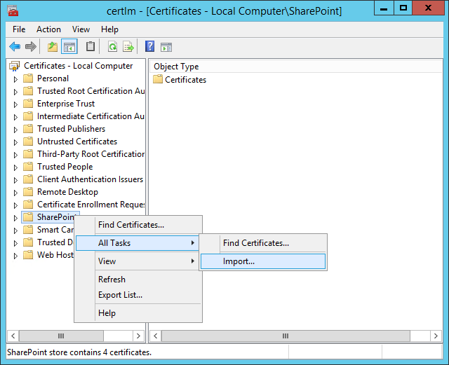
In the Certificate Import Wizard window that opens, click Next.
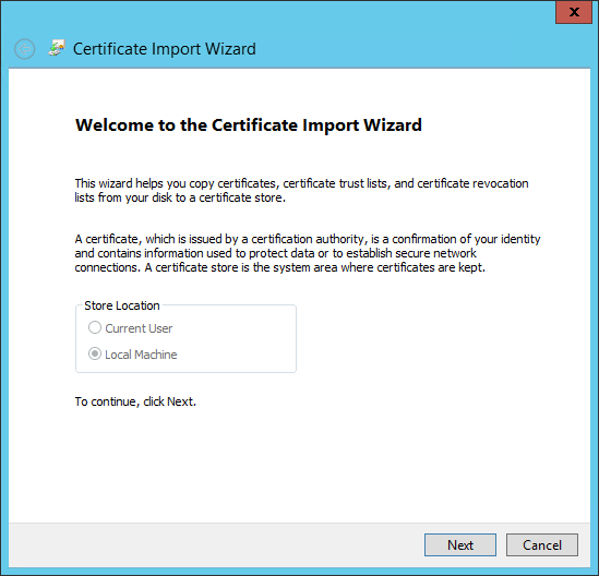
In the Certificate Import Wizard window, on the File to Import screen, click Browse to find the self-signed certificate we created in the previous sub-section.

In the File Explorer window that opens automatically, click through location folders to find the self-signed certificate we created in the previous sub-section (example from this build: C:/Windows/System32/).
Find the certificate and click to select it; then click Open.
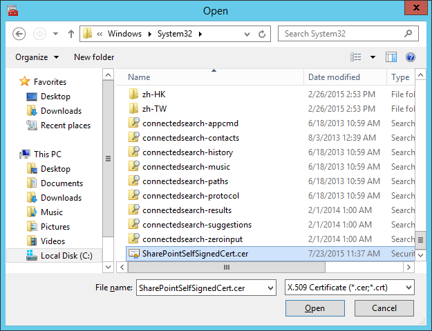
Back at the Certificate Import Wizard, on the File to Import screen, the location of the self-signed certificate will be in the File name field. Click Next.
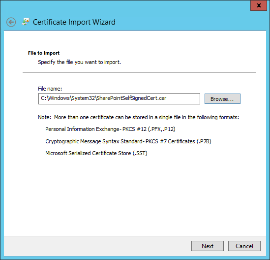
In the Certificate Import Wizard window on the Certificate Store screen, leave the default radio button for Place all certificates in the following store chosen. The Certificate store field should be set to SharePoint. Click Next.
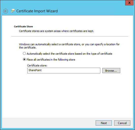
In the Certificate Import Wizard window, click Finish.
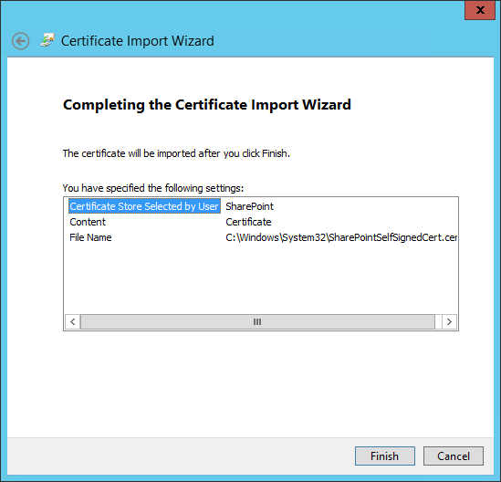
In the Certificate Import Wizard window that automatically opens, you will see a message that the import was successful. Click OK.

In the certlm window, double-click on Certificates under the SharePoint node. The new self-signed certificate you created will be listed there.
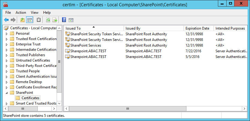
Open File Explorer and click through locations to reach the location of your self-signed certificate (from this example: C:/Windows/System32/).
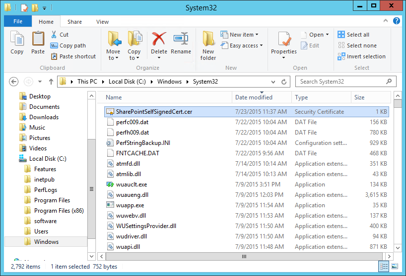
Right-click on the self-signed certificate and click on Copy or left-click on the self-signed certificate and press the keys Ctrl+C.
Right-click on your Desktop and click Paste, or left-click on your Desktop and press the keys Ctrl+V to save a copy of the certificate in an accessible location.
To Manage Trust via Central Administration, do the following steps: Open a browser.
In the URL address bar of the browser, enter the address for Central Administration and click Enter or Go: http://sharepoint:44444/default.aspx
From the Central Administration page, click on Security in the left-hand menu.
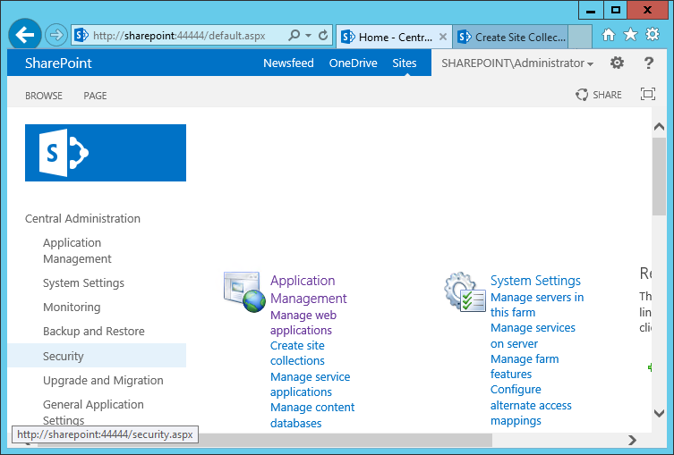
From the Security page, under the General Security section, click on Manage Trust.
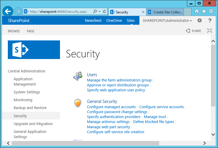
Under the Trust Relationships tab of the Manage Trust page, click New.
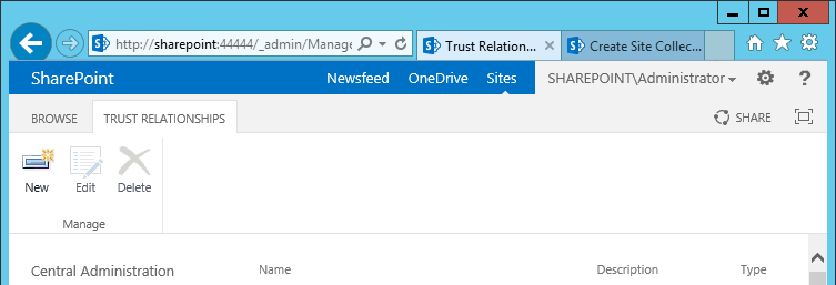
In the Establish Trust Relationship window that opens automatically, enter the Name for the trust relationship being created, then click Browse to find the certificate created in previous sub-sections.
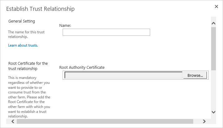
In the Choose File to Upload window that opens automatically, navigate to the copy of your certificate from Section 4.4.1.1 (e.g., Desktop). Click on the certificate so its name automatically fills the File name field at the bottom of the window, then click Open.
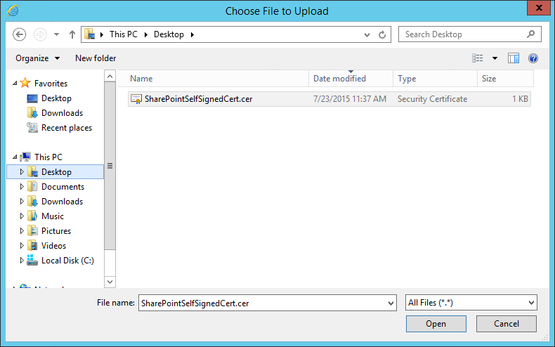
In the Establish Trust Relationship window, the certificate’s location will be automatically entered as the Root Authority Certificate.
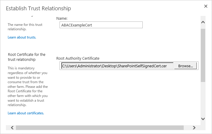
In the Establish Trust Relationship window, scroll down leaving the remaining fields empty, and click OK.
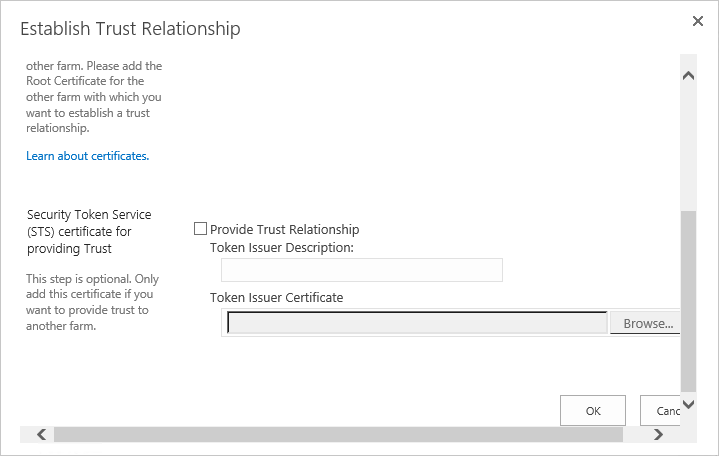
Your new trust relationship will be listed under the Trust Relationships tab.
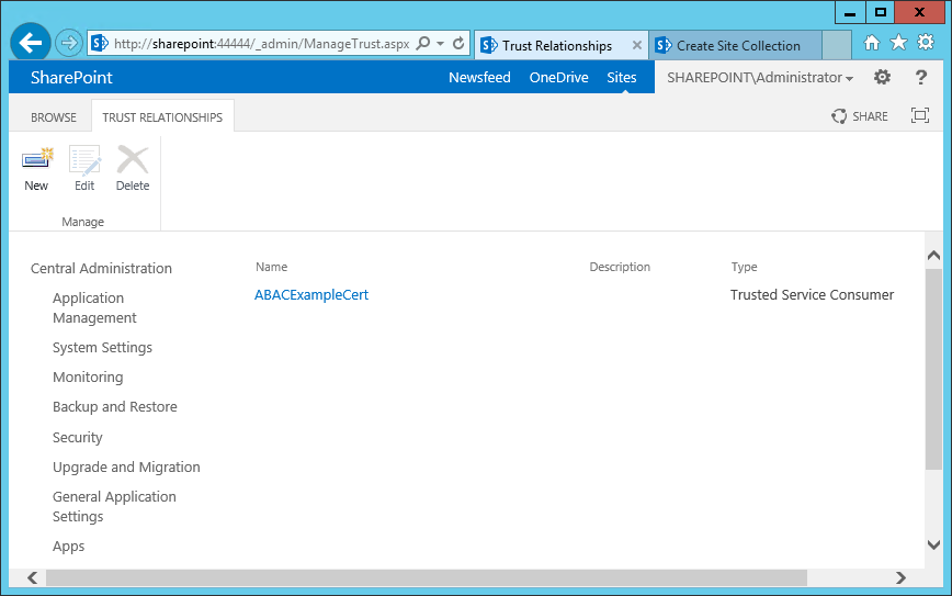
4.4.1.4. Configure IIS Binding for the Self-Signed Certificate
Click on the Windows icon in the bottom left corner of your screen.
Begin typing IIS.
When the Internet Information Services (IIS) Manager appears, click on it.
On the left-hand side of the IIS Manager window, click on the SharePoint web application created in previous steps, then click Bindings in the Actions pane on the right.
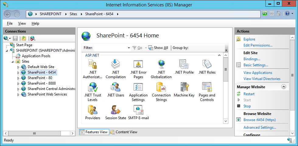
In the Site Bindings window that opens, look for a binding type of https.
- If a binding type of https does not exist, click on Add.
- If a binding type of https does already exist, click on it, then click Edit.
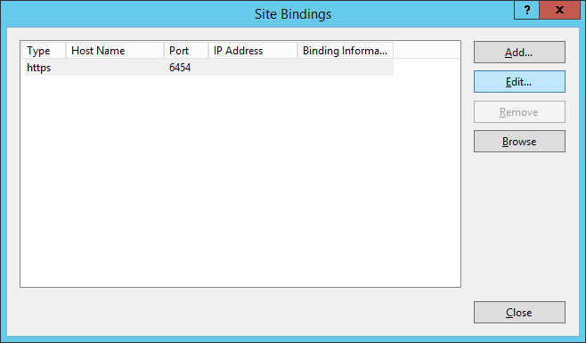
In the Edit Site Binding window next to the SSL certificate field, click Select.
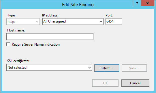
In the Select Certificate window, click on the certificate created in previous steps and click OK.
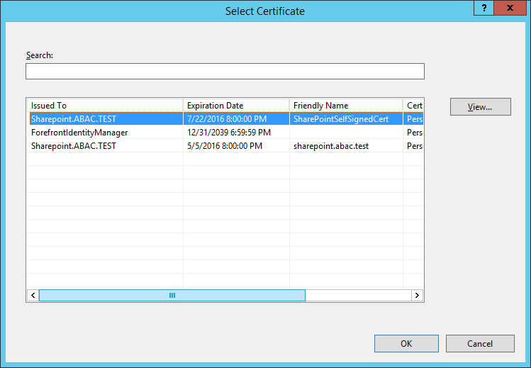
In the Edit Site Binding window, verify that your SSL certificate is listed, then click OK.
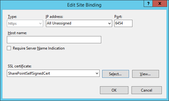
In the Site Bindings window, click Close.
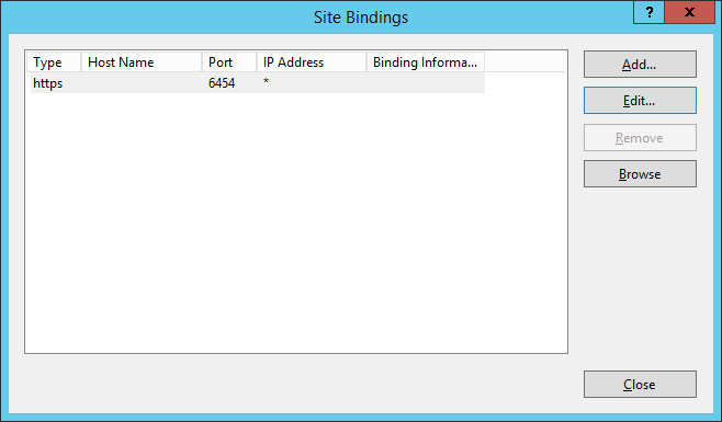
4.4.2. Certificates Signed by Local or Online Certificate Authority
Instead of using self-signed certificates which can be used in protected lab environments, it is recommended that you use certificates signed by a Certificate Authority. For our build, we used Symantec’s Managed PKI Service to sign our certificates using a local Certificate Authority. Certificates were used to support various exchanges that require encryption, such as digital signature, SAML message encryption, and encryption of TLS communications.
Although the detailed instructions of configuring certificates signed by a certificate authority vary by vendor product, the general process is described below. For each certificate, you perform the following high-level steps:
- Using the vendor product (e.g., SharePoint), generate a certificate signing request on the server where you want to use the certificate. Save the signing request to a file.
- Submit an enrollment request to your certificate authority. You will need to provide the signing request that was generated in step 1. This step is typically where you provide information such as the name of the server on which you intend to use the certificate (e.g., “sharepoint.abac.test”).
- A representative at the certificate authority will examine the enrollment request and approve it. The representative will issue a certificate response signed with the certificate authority’s key. You can download the signed response. If you are using a certificate authority that is locally managed by your organization, you will also need to download the public key of the certificate authority because you will need to add this to the Trusted Certificate Authorities on each server and client that will be using the certificates.
- Go back to the vendor product where you created the certificate signing request. If you are using a local certificate authority, you will first need to add the certificate authority’s public key to the list of Trusted Certificate Authorities.
- Import the certificate file for your server that was signed by the certificate authority.
4.4.2.1. Generating a Certificate Signing Request (CSR)
Log into the server where SharePoint Server 2013 is installed (e.g., SharePoint Server in our build).
Click on the Windows icon in the bottom left corner of your screen.
Begin typing IIS.
When the Internet Information Services (IIS) Manager appears, click on it.
In the left-hand Connections column, left-click on your SharePoint instance.
Scroll down in the SharePoint Home pane and left-click on Server Certificates.
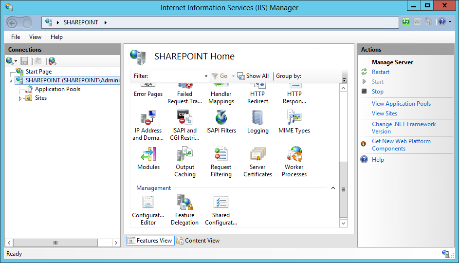
In the right-hand Actions column, click on Open Feature.

In the Server Certificates pane, in the right-hand Actions column, click on Create Certificate Request.

In the Distinguished Name Properties window that opens automatically, enter your organizational information and click Next.
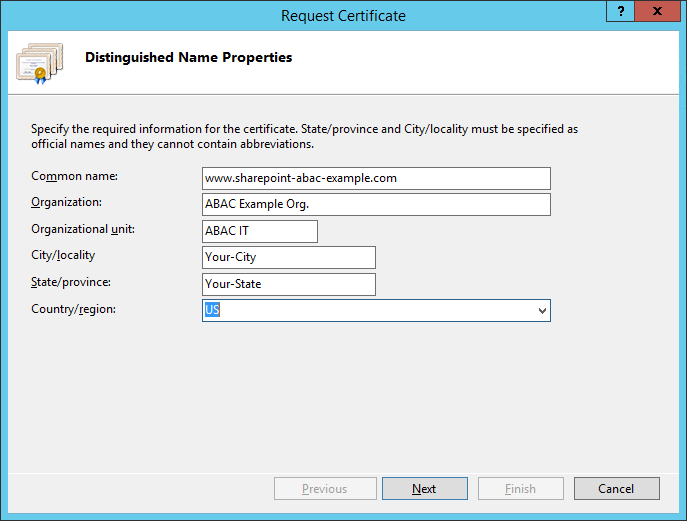
In the Cryptographic Service Provider Properties window that opens automatically, choose the Cryptographic service provider and a Bit length, then click Next.

On the File Name screen, browse to the location where you would like to save this certificate or type in the path, including a name for your certificate ending in “.txt,” then click Finish.
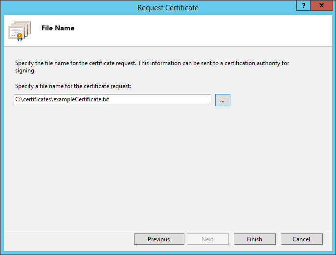
4.4.2.2. Installing the new signed SSL Certificate
When the new signed SSL Certificate is available either from a local or online Certificate Authority, install the certificate using the instructions in this section.
Log onto the SharePoint Server and save the SSL certificate resulting from the CSR in Section 4.2.1.
Click on the Windows icon in the bottom left corner of your screen.
Begin typing IIS.
When the Internet Information Services (IIS) Manager appears, click on it.
In the left-hand Connections column, left-click on your SharePoint instance.
Scroll down in the SharePoint Home pane and left-click on Server Certificates.
In the right-hand Actions column, click on Open Feature.
In the Server Certificates pane, in the right-hand Actions column, click on Complete Certificate Request.
In the Complete Certificate Request wizard on the Specify Certificate Authority Response screen, browse to the location of the new SSL certificate generated from your CSR or type in its location, enter a friendly name, and choose a certificate store from the drop-down menu. Click OK.
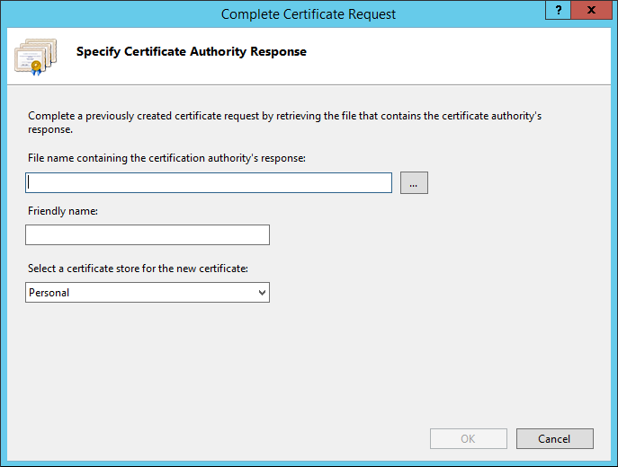
4.4.2.3. Configure the CA-Signed Certificate
Follow the steps listed in Section 4.4.1.4 to configure IIS Binding for the new SSL certificate signed by a local or online Certificate Authority. You can choose port 443 or any other available port if you prefer to use a non-standard port for SSL traffic.
4.5. Creating a Site Collection
On the SharePoint Server, open a web browser.
In the URL address bar of the browser, enter the address for Central Administration and click Enter or Go: http://sharepoint:44444/default.aspx
From the Central Administration page, in the Application Management section, click on Create site collections.
On the Create Site Collection page, do the following:
- Verify that the web application under consideration is the one chosen.
- Enter a Title (required) and Description (optional).
- Choose the web site address you prefer for your site (in this build, https://sharepoint:6454/).
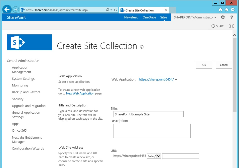
In the browser, scroll down to the Template Selection area and Primary Site Collection Administrator area of the Create Site Selection page and do the following:
Choose the version and template (e.g., 2013 Team Site)
In the User name field, under the Primary Site Collection Administrator area, type in the name of your SharePoint Administrator account and click on the Name check icon. If the name is found, it will not give a warning and the name will be underlined.
- Alternatively, you can look up users by name using the address book people picker mechanism next to the user name text field.
In the User name field under the Primary Site Collection Administrator area, type in the name of a secondary administrator if you so choose.
- Alternatively, you can look up users by name using the address book people picker mechanism next to the user name text field.
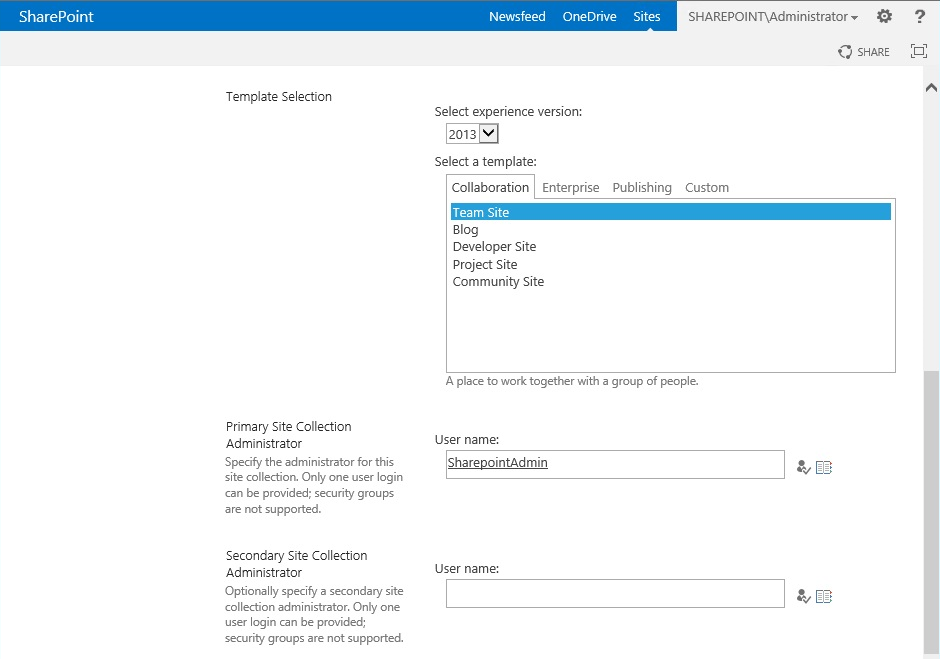
Scroll down in the browser to the Quota Template area of the Create Site Collection page. Leave the default choice No Quota chosen. Click OK.
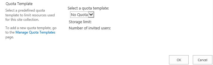
Wait for the Site Collection to successfully complete.
In the browser, on the page that indicates a new top-level site was created successfully, click OK.
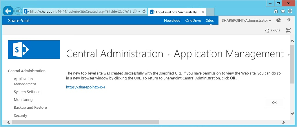
Open a browser and navigate to the URL for your new web application (e.g., https://sharepoint:6454)
You may see a warning first because of the self-signing certificate.
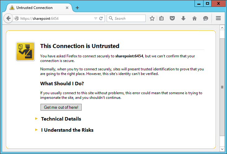
In the browser window, click on I Understand the Risks, then Add Exception.
In the Add Security Exception window, click on Confirm Security Exception.
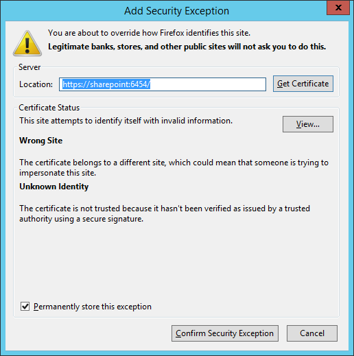
In the Authentication Required window that opens automatically, enter the administrator account User Name and Password, then click OK.
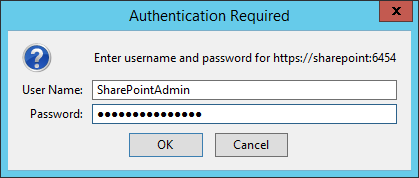
Upon verification that the login was a success, you will see default site contents.
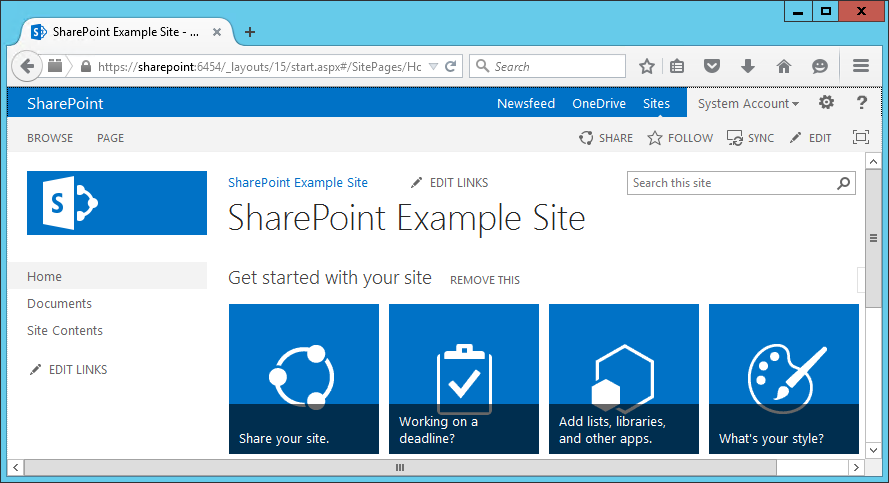
4.6. Creating New Sub-Sites
After logging into your site, in your browser window click the gear symbol next to the Administrator login area, then click on Site Contents.
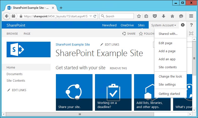
In the browser window, the Site Contents page will open.
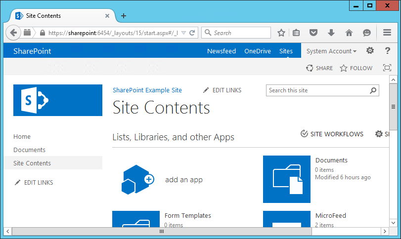
In the browser window, scroll down to the Subsites area and click the plus sign button next to new subsite.
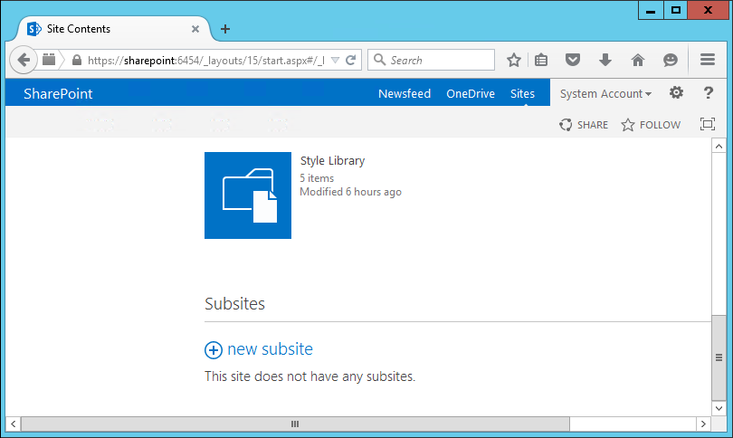
In the browser window on the New SharePoint Site screen, do the following:
- Enter Title (required) and Description (optional).
- Enter a URL name.
- Select a template.
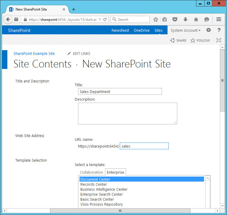
In your browser, scroll down and do the following:
- Choose User Permissions (in our build, we left the Use same permissions as parent site radio button selected).
- Choose your Navigation and Navigation Inheritance settings.
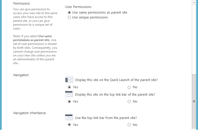
In the browser, scroll down and click Create.
Your new subsite will open in the browser.
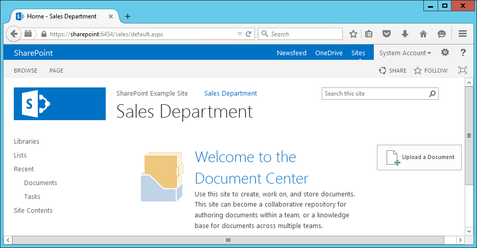
Return to the homepage URL https://sharepoint:6454 and repeat the steps from Section 4.6 to create other subsites of interest.
5. Set Up Federated Authentication at the Relying Party’s SharePoint
5.1. Introduction
In previous sections of this How-To Guide we demonstrated how to set up set up federated authentication between the relying party and the identity provider and how to create the relying party’s SharePoint site. In this section, we demonstrate how to set up federated authentication between the relying party’s SharePoint and the PingFederate-RP. Before continuing with this section implementers are required to have federation servers at both the identity provider and the relying party as well as a working SharePoint instance that is claims-aware. For this build we provide instructions for setting up these components in Section 2, Section 3, and Section 4.
We will demonstrate how to set up a trusted logon provider for the relying party’ so that when a user requests access to a SharePoint site, the user will be redirected to the PingFederate-RP for authentication via WS-Federation. The Ping-Federate-RP will then forward the authentication request to the PingFederate-IdP. The PingFederate-IdP will present a logon page to the user. Once the user authenticates, the user will be redirected back to the original SharePoint site and will be able to access the site because they have a valid authentication token.
As you complete different steps in this section you will be able to verify the correctness or completeness of your component configuration and integration in Functional Test sub-sections.
If you follow the instructions in this How-To Guide section, you will be able to perform a Functional Test to verify the successful completion of the steps for installing, configuring, and integrating the components.
5.2. Usage Notes on PingFederate
- When using the PingFederate application to perform an administrative configuration, there is usually a sequence of screens, ending with a summary page. Once you click Done on the summary page, you must also click Save on the following page to save the configurations. If you forget to click Save, you may inadvertently lose changes to the configuration.
- Ping identity refers to the relying party as the Service Provider in their PingFederate product and associated documentation.
- When using the PingFederate application to perform configuration, refer to the title of the tab with a small star icon to its left, to easily identify the item you are currently configuring. For example, if you navigated to the following screen, you would be on the IdP Adapter screen.
5.3. Configure a SharePoint Federated Logon Provider
Follow the instructions in this section to configure the federated logon provider at the relying party’s SharePoint site. Once this configuration is complete, the user will see two authentication options when first attempting to access the SharePoint site. The first option is to log on using the default Windows Authentication. This option does not use federation. The second option is to use a federated logon.
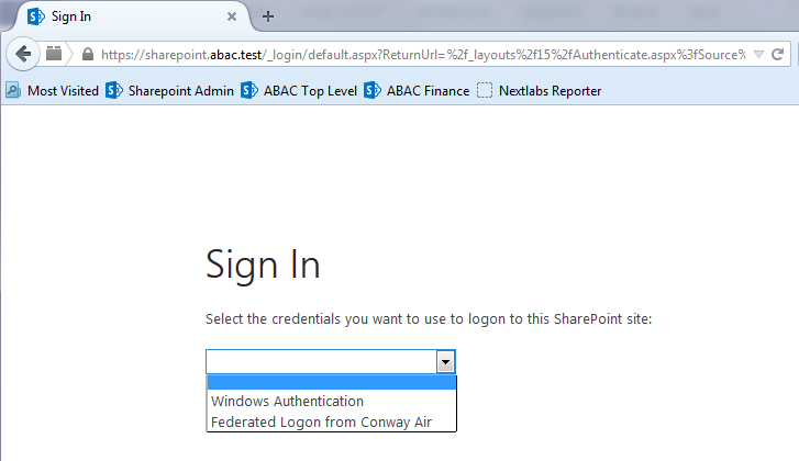
In order to set up a federated logon, you will configure a trust relationship between the SharePoint server and the PingFederate-RP that will facilitate the federated logon. Once a user authenticates via a federated logon, the PingFederate-RP will cryptographically sign WS-Federation messages and send them to the SharePoint server. The PingFederate-RP must be configured as a trusted identity token Issuer in SharePoint, so that SharePoint will accept the messages sent by the PingFederate-RP and allow the user access to the SharePoint site.
5.3.1. Setting up the Certificate
Setting up a certificate involves creating the certificate at the from the identity provider, exporting the certificate, and importing it in the SharePoint site of the relying party.
Logon to the server that hosts the PingFederate service for the relying party.
Launch your browser and go to: https://<DNS_NAME>:9999/pingfederate/app.
Replace DNS_NAME with the fully qualified name of the relying party’s PingFederate server (e.g., https://rp.abac.test:9999/pingfederate/app).
Logon to the PingFederate application using the credentials you configured during installation.
On the Main Menu, under CERTIFICATE MANAGEMENT, click Digital Signing and XML.
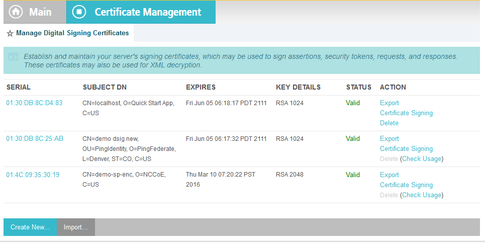
Locate the certificate that will be used to sign messages that will be sent to the SharePoint server. In the example screenshot above, this certificate has CN with the value demo dsig new. Click on the Export link for this certificate in the ACTION column.
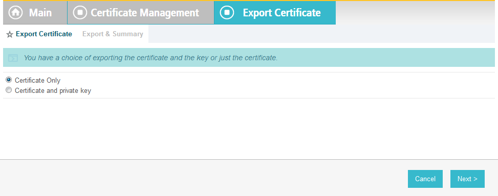
Select Certificate Only and click Next.
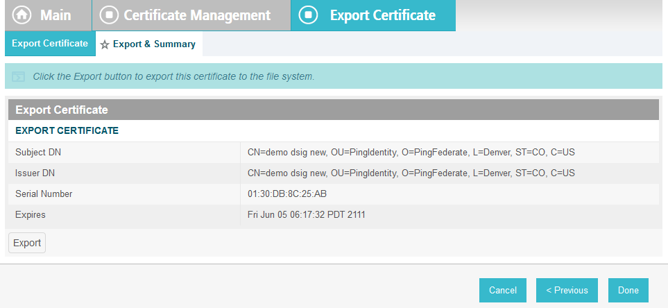
On the Export & Summary page, click the Export button on the left side of the page. Save the file to the hard drive and rename it to federation.cer.
Using the SharePoint administrator credentials, logon to the server that hosts SharePoint for the relying party.
Copy the federation.cer file to the desktop on the SharePoint server.
Click on the Start menu and navigate to the SharePoint 2013 Products group. Open the SharePoint 2013 Management Shell.
To verify that you placed the federation.cer file to the desktop, enter the following command into the Management Shell (using the correct path for your server).
dir c:\users\SharePointadmin\desktop\federation.cerYou should see information about the file such as the LastWriteTime.
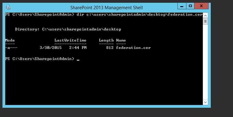
Enter the following commands into the Management Shell to import the PingFederate-RP’s signing certificate (using the correct path for your server):
$cert = New-Object System.Security.Cryptography.X509Certificates.X509Certificate2("C:\users\SharePointadmin\Desktop\federation.cer")

New-SPTrustedRootAuthority -Name "Federated Token Signing Cert" -Certificate $cert
SharePoint responds by displaying details about the imported certificate.
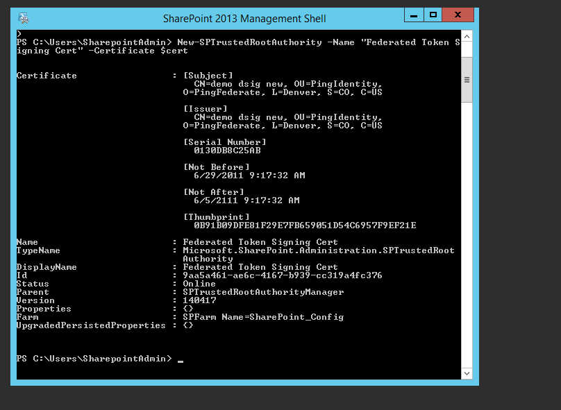
5.3.2. Configuring the Trusted Identity Token Issuer
To configure a new Trusted Identity Token Issuer, enter each of the commands displayed below the next paragraph into the Management Shell to configure a new Trusted Identity Token Issuer. Enter each command separately, and enter a Carriage Return after the command. If the command executed successfully, Management Shell will not provide any feedback. If an error occurs, Management Shell will display the error.
In the example commands below, the attribute upn is configured. You can replace upn with an attribute that is appropriate for your environment. The realm value (e.g., urn:SharePoint.abac.test) must be identical to the realm value configured in the relying party’s PingFederate Service Provider (SP) connection that will be configured later in this section. The signInURL should be configured with the PingFederate-RP WS-Federation URL (e.g., https://rp.abac.test:9031/idp/prp.wsf). In this example, the name given to this new token issuer in SharePoint is Federated Logon from Identity Provider. The issuer name will be displayed in SharePoint administration screens and to the end user on the Sign On screen.
$claimmap = New-SPClaimTypeMapping -IncomingClaimType "http://schemas.xmlsoap.org/ws/2005/05/identity/claims/upn" -IncomingClaimTypeDisplayName "upn" –SameAsIncoming

$realm = "urn:SharePoint.abac.test"

$signInURL = https://rp.abac.test:9031/idp/prp.wsf

$ap = New-SPTrustedIdentityTokenIssuer -Name "Federated Logon from Identity Provider" -Description "Federated Logon" -realm $realm -ImportTrustCertificate $cert -ClaimsMappings $claimmap -SignInUrl $signInURL -IdentifierClaim $claimmap.InputClaimType
5.3.3. Configuring the Token Issuer as a Sign On Option
After configuring the new Trusted Identity Token Issuer, configure the new token issuer as a Sign On option for the SharePoint site.
Launch your browser and go the SharePoint central administration page (e.g., http://SharePoint.abac.test:44444/default.aspx).
Logon using the credentials of the SharePoint administrator
In the Application Management group, click on Manage web applications.
Click on the web application that contains the SharePoint site you are managing (e.g., SharePoint – 80). SharePoint will highlight the web application row that you clicked on.
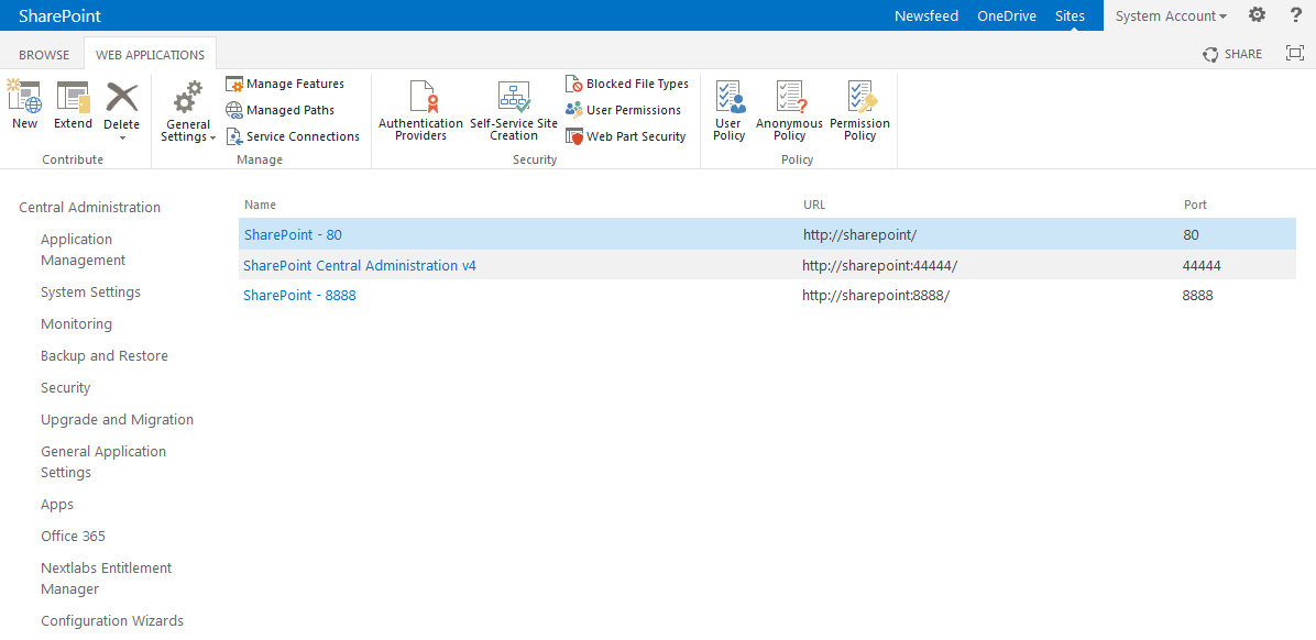
Click on the Authentication Providers button at the top of the page.
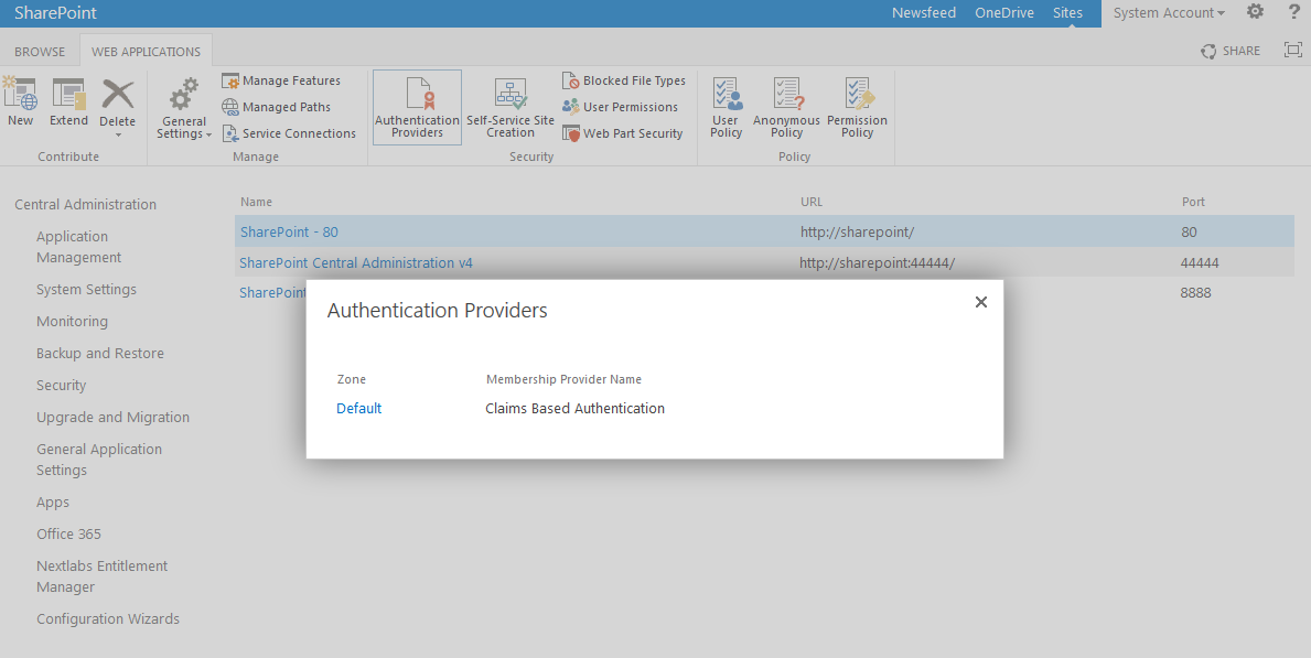
Click on the Default link in the Zone column.
On the Edit Authentication screen, scroll down to the Claims Authentication Types group. Select the Trusted Identity provider option.
Under the Trusted Identity provider checkbox, select the name of the new token issuer that was created using the Powershell commands (e.g., Federated Logon from Identity Provider).

Scroll to the bottom of the page and click Save.
5.3.4. Configuring the Access Control Rule on SharePoint
After configuring the token issuer as a Sign On option for SharePoint, configure the access control rule on the SharePoint site that is necessary for federated users to be able to access the site.
Logon to the relying party’s SharePoint site (e.g., https://SharePoint.abac.test) using the credentials of the SharePoint administrator.
Select Windows Authentication in the Sign On screen.
Click the gear icon at the top right corner of the page and select the Site Settings link.
On the Site Settings screen, in the Users and Permissions group, click People and Groups.
Under the Groups heading on the left pane, click on the HOME Members group.
Under the page title, click on the New link and select the Add Users option from the popup menu.
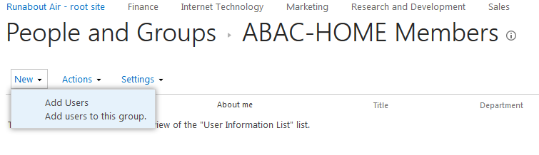
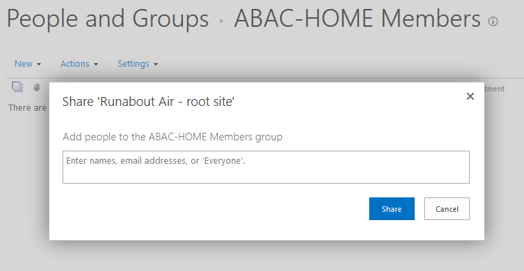
On the Share popup screen, enter Everyone in the text field.
SharePoint will display a List Box underneath the text field.
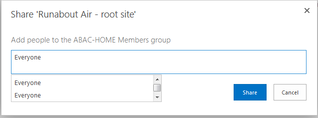
The list will contain multiple entries for the same value of Everyone. If you place your cursor over an entry in the list SharePoint will display details about the entry.

Locate the entry that is associated with All Users.
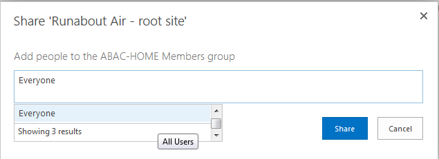
Click on the entry associated with All Users.
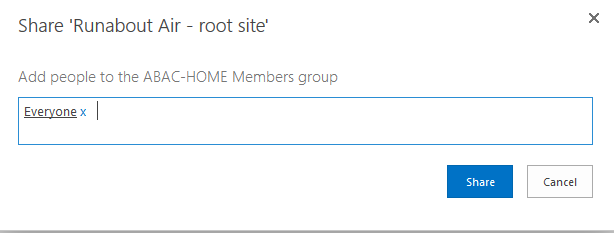
Click Share.
When you go back to the People and Groups screen, you should see Everyone listed for the Home Members group.
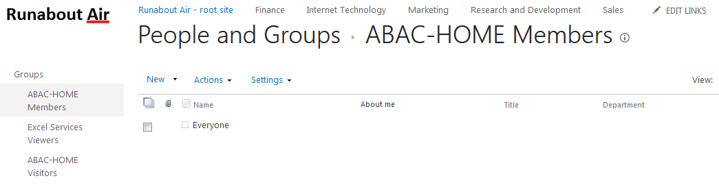
5.3.5. Functional Test of the Federated Logon at the Resource Provider
Launch a new browser window and go to the relying party’s SharePoint site (e.g., https://SharePoint.abac.test).
Expected Result: You should see two logon options in the dropdown box. One of the options should be the name of the new trusted token issuer that was configured in the previous section (e.g., Federated Logon from Identity Provider).
Next you will verify that SharePoint is configured to read the upn attribute that was configured for the federated logon.
Launch your browser and go the SharePoint central administration page (e.g., http://SharePoint.abac.test:44444/default.aspx).
Logon using the credentials of the SharePoint administrator.
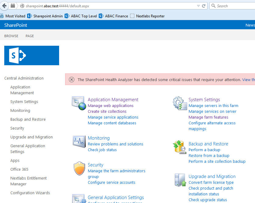
In the Application Management group, click on Manage web applications.
Click on the web application that contains the SharePoint site you are managing (e.g., SharePoint – 80). SharePoint will highlight the web application row that you clicked on.

Click on the User Policy button.
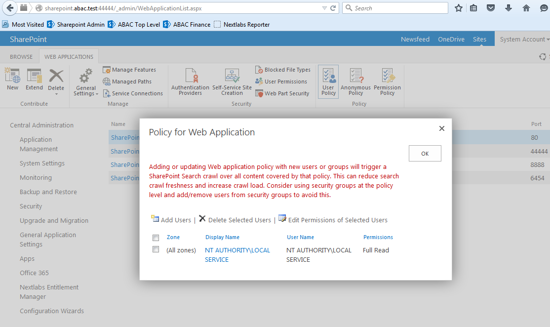
Click Add Users.
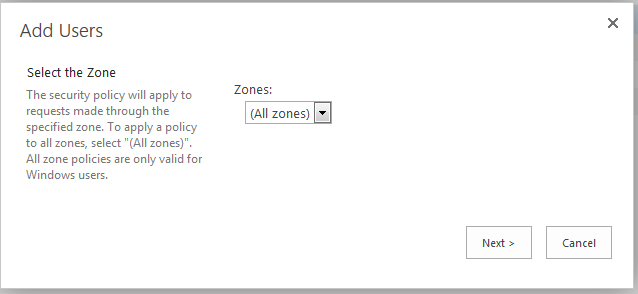
Click Next.
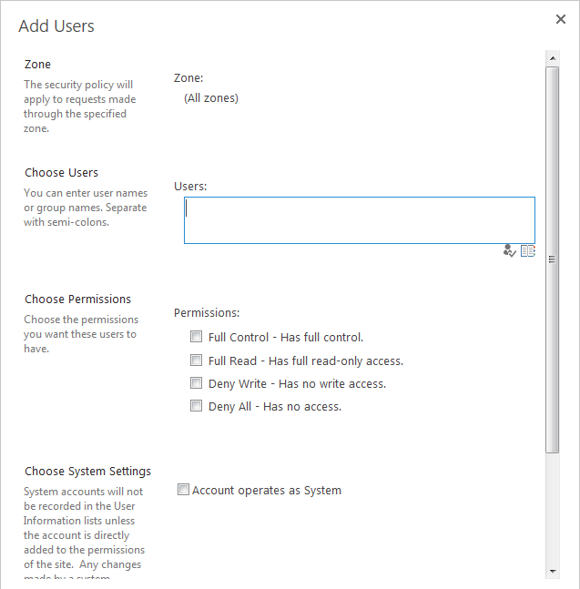
On the Add Users screen, click the small browse icon (looks like a book) under the Users field.
Expected Result: On the Select People and Groups screen, you should see a grouping with the name of the trusted token issuer that was configured via Powershell (e.g., Federated Logon from Identity Provider). You should also see the upn attribute listed under that grouping.
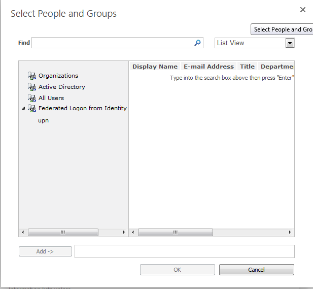
5.4. Configure the PingFederate-RP Connection to SharePoint
Follow the instructions below to configure a PingFederate connection from the PingFederate-RP to the relying party’s SharePoint.
Logon to the server that hosts the PingFederate service for the relying party.
Launch your browser and go to: https://<DNS_NAME>:9999/pingfederate/app. Replace DNS_NAME with the fully qualified name of the relying party’s PingFederate server (e.g., https://rp.abac.test:9999/pingfederate/app). Logon to the PingFederate application using the credentials you configured during installation.
On the Main Menu under SP CONNECTIONS, click Create New. On the Connection Type screen, select Browser SSO Profiles. For the Protocol field, select WS-Federation.
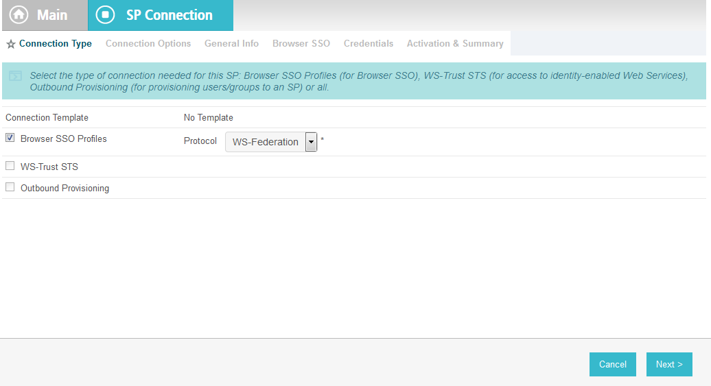
Click Next. On the Connection Options screen, select Browser SSO.
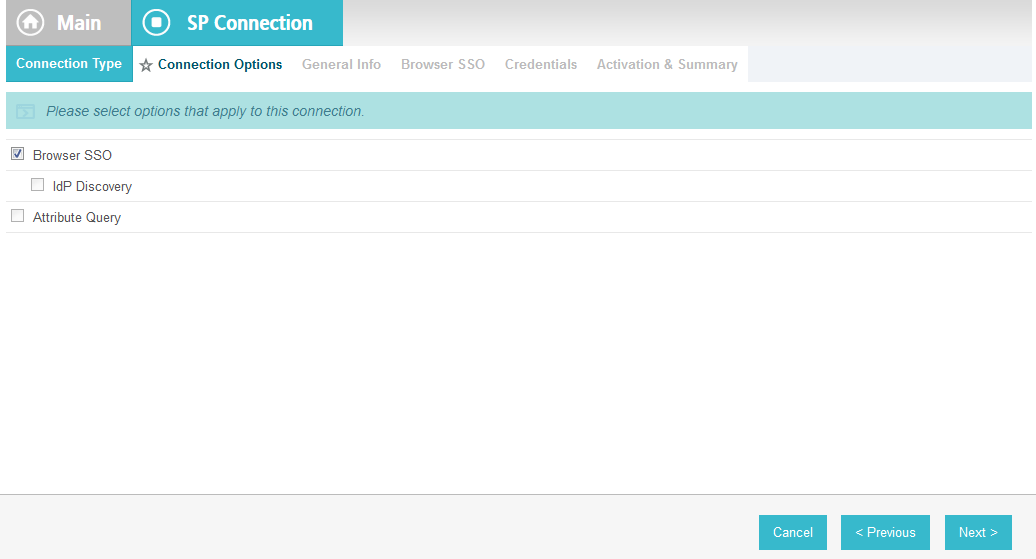
Click Next. On the General Info screen, for the Partner’s Realm field, enter the name of the Resource Provider’s (SharePoint) realm (e.g., urn:SharePoint.abac.test). Keep a copy of the realm name because it will be used in a configuration of SharePoint later in the guide.
Enter a unique name for this new PingFederate configuration in the Connection Name field. For the Base URL field, enter the root destination URL at the SharePoint site where the PingFederate will redirect a user once authenticated (e.g., https://SharePoint.abac.test).
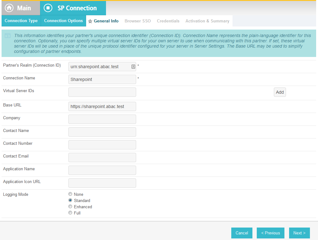
Click Next.
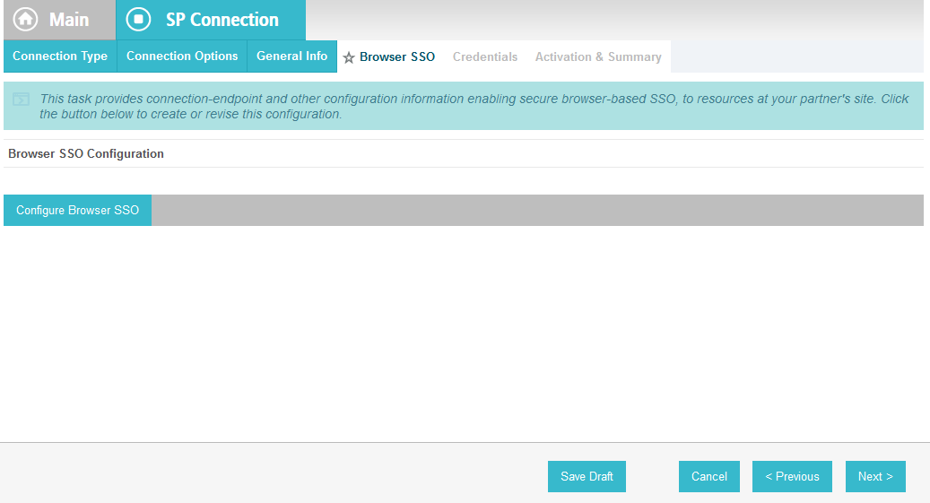
On the Browser SSO screen, click Configure Browser SSO. On the Assertion Lifetime screen, enter a value of 20 for the Minutes After field.
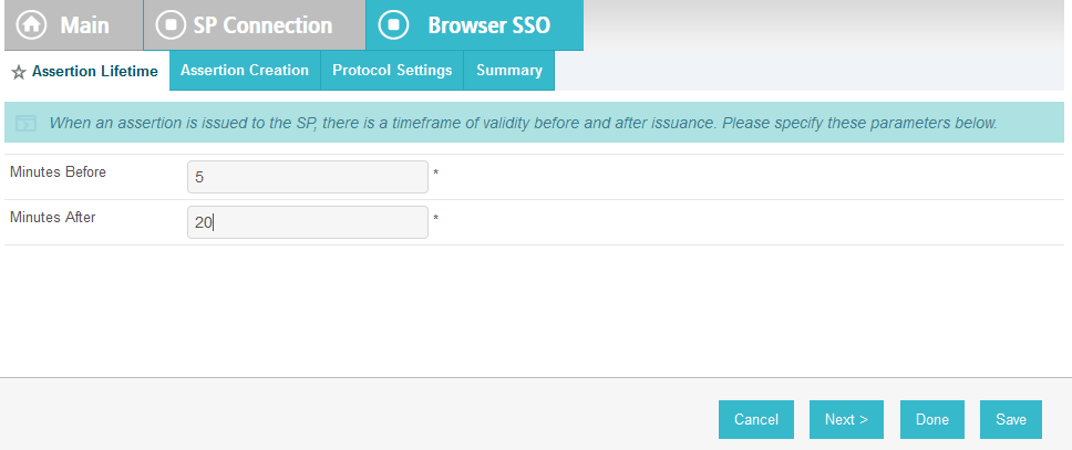
Click Next.

On the Assertion Creation screen, click Configure Assertion Creation. On the Identity Mapping screen, select User Principal Name.
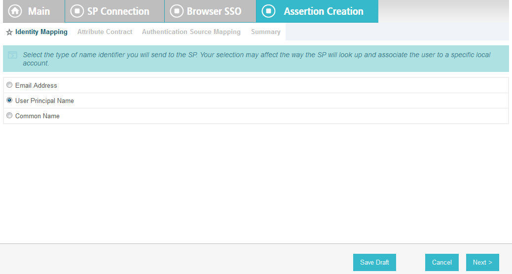
Click Next. On the Attribute Contract screen, below the EXTEND THE CONTRACT FIELD, enter “upn” in the textbox. For the ATTRIBUTE NAME FORMAT select the schemas.xmlsoap.org 2005 identity claims format.
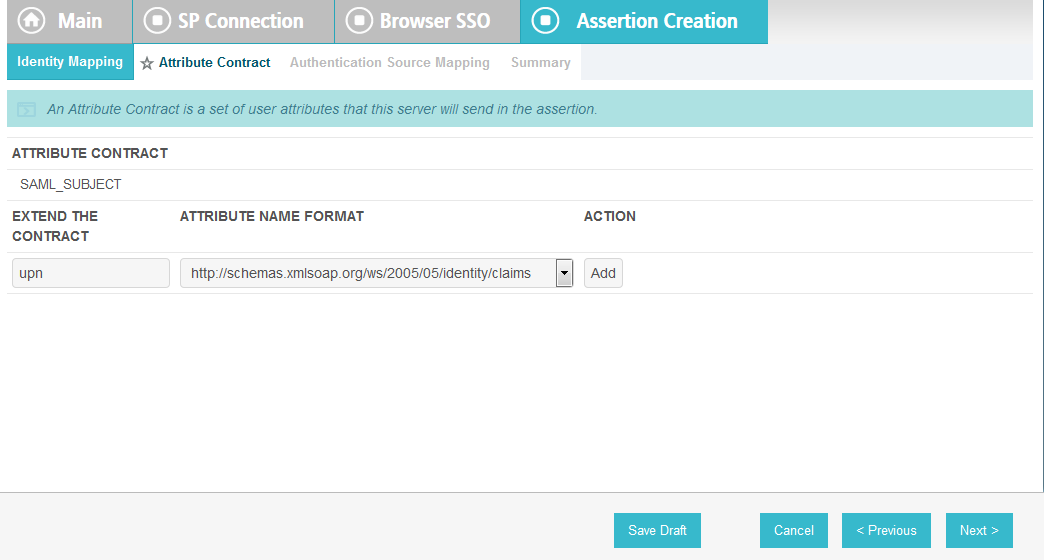
Click Add.
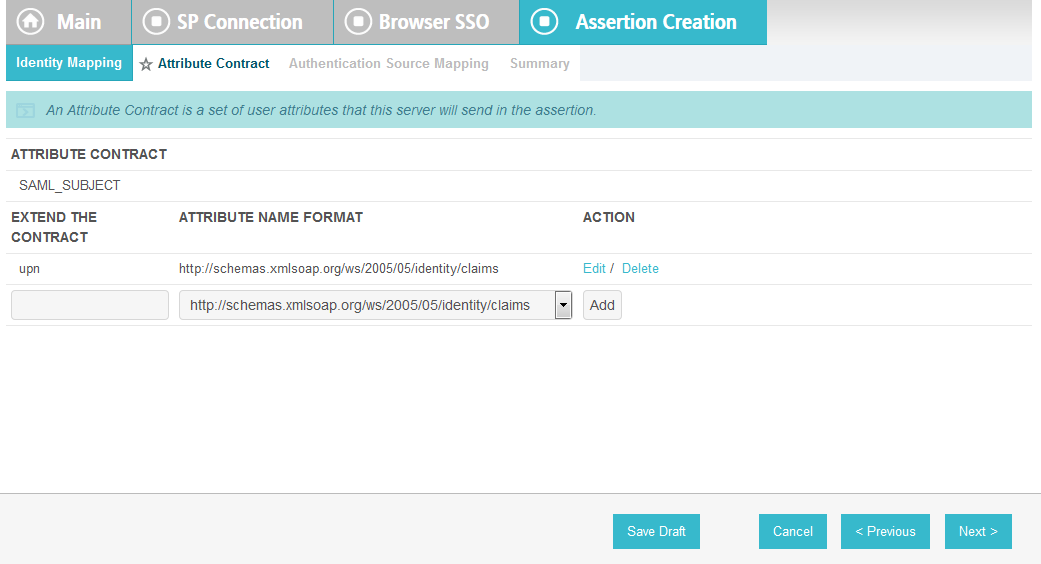
Click Next.

On the Authentication Source Mapping screen, click Map New Connection Contract Mapping. On the Connection Contract Mapping screen, for the CONNECTION MAPPING CONTRACT field, select the name of the contract with the identity provider that was configured in a Section 3 (e.g., SharePoint 2013).
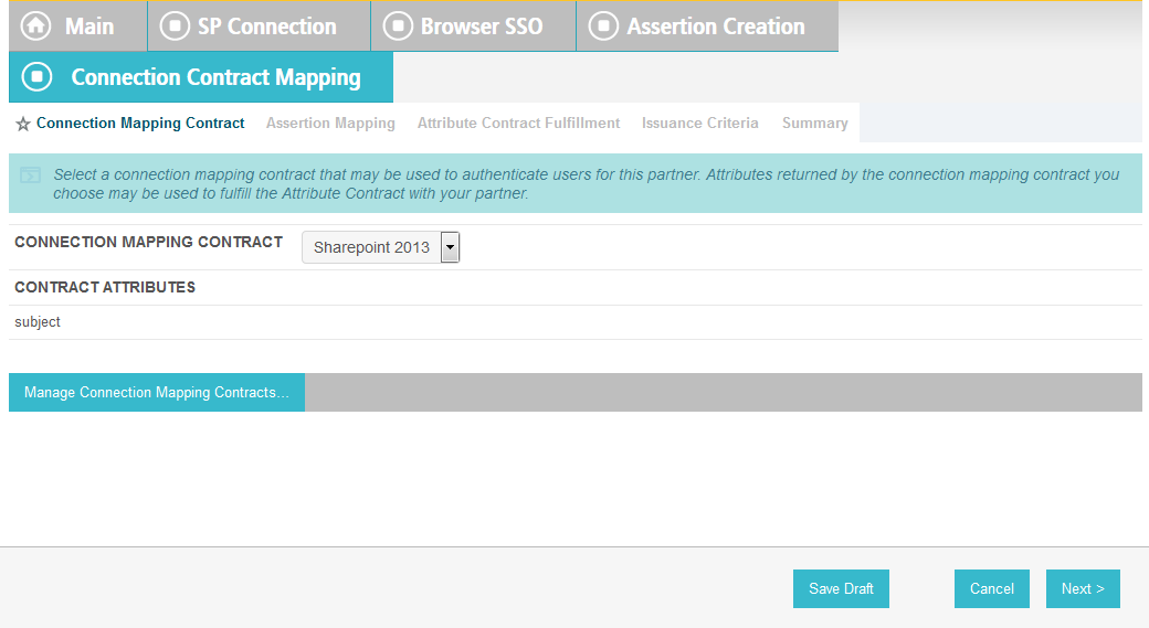
Click Next. On the Assertion Mapping screen, select Use only the Connection Mapping Contract values in the SAML assertion.
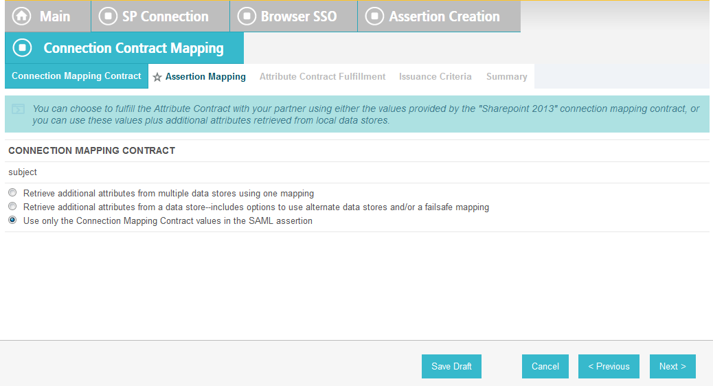
Click Next.
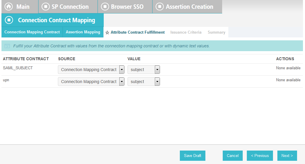
On the Attribute Contract Fulfillment screen, click Next.
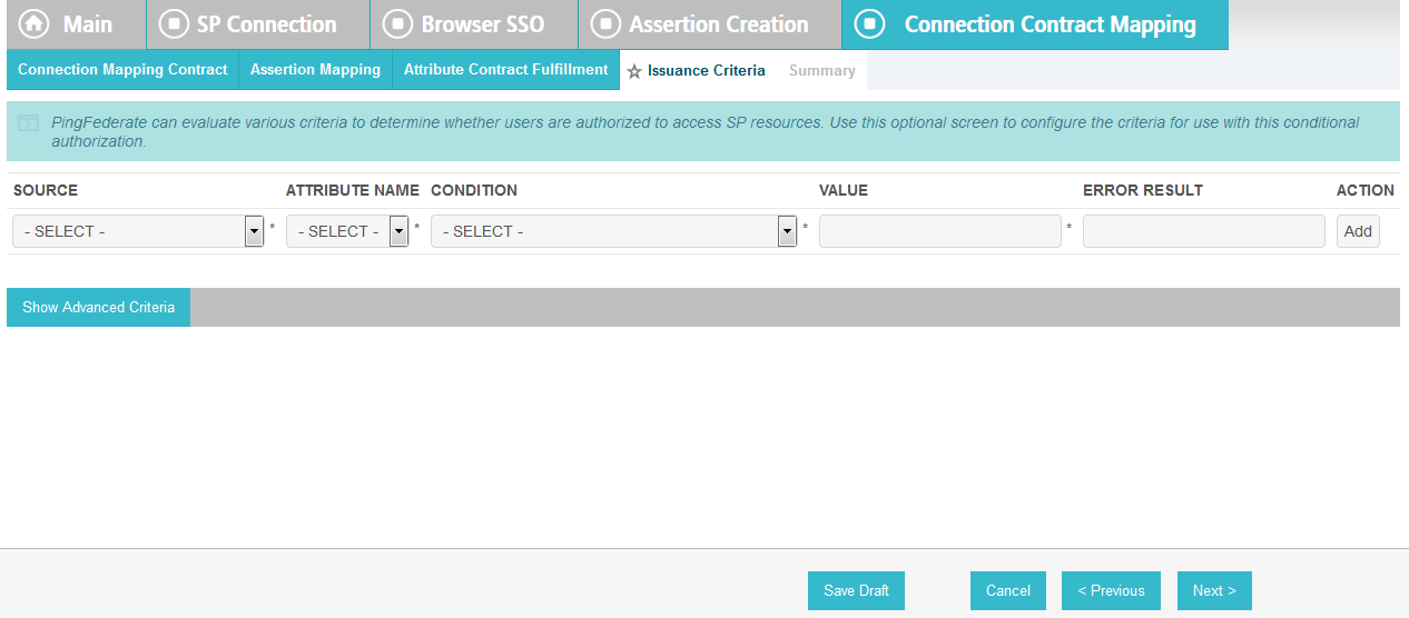
On the Issuance Criteria screen, click Next.
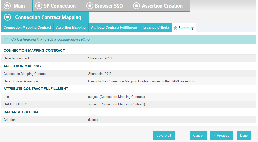
On the Summary screen, click Next.
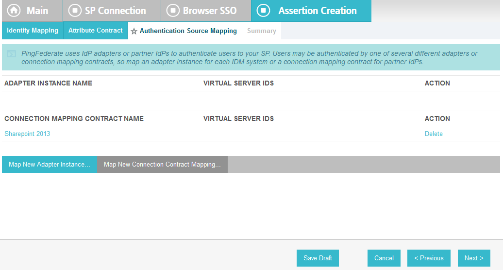
On the Authentication Source Mapping screen, click Next.
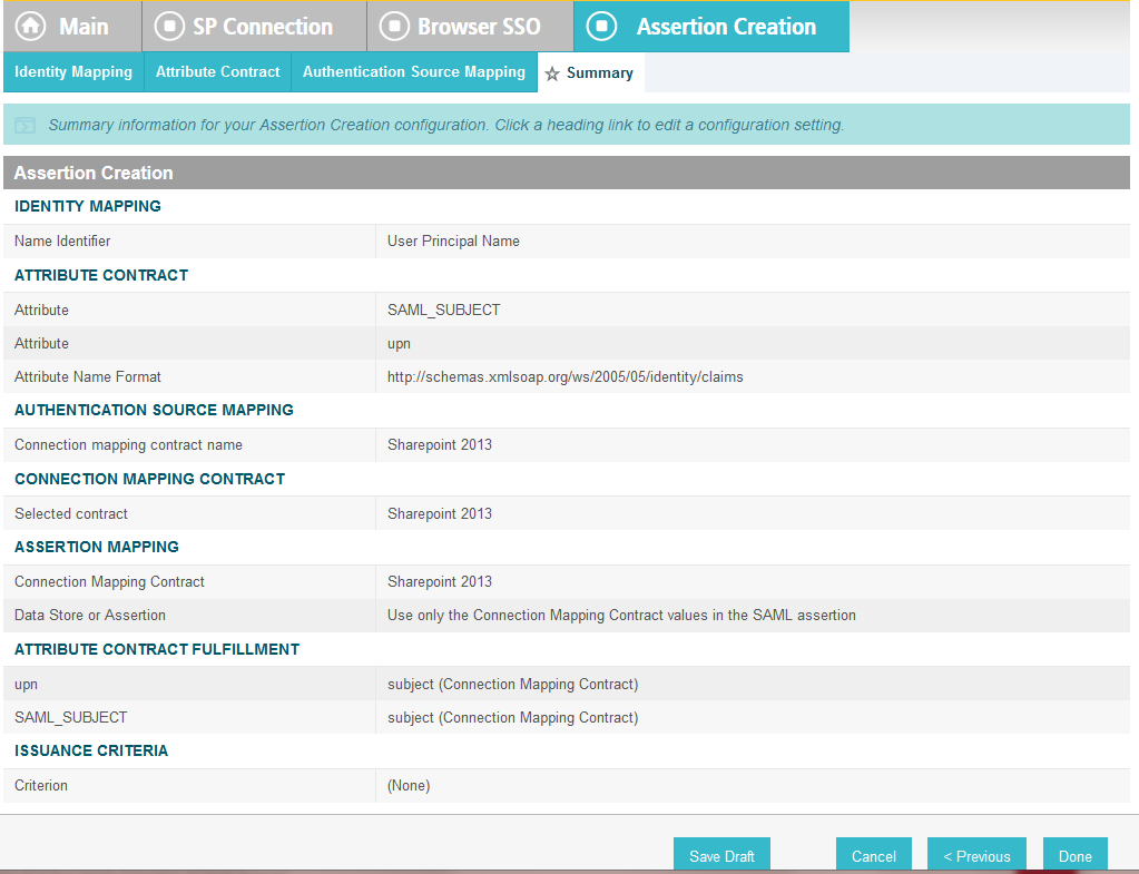
On the Summary screen, click Done.
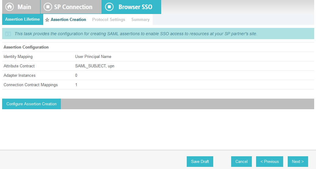
On the Assertion Creation screen, click Next.
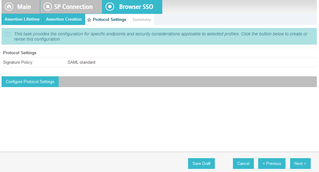
On the Protocol Settings screen, click Configure Protocol Settings. On the Service URL screen, for the Endpoint URL field, enter the name of the destination URL at the Service Provider (SharePoint) site (.e.g., /_trust/). When PingFederate completes the authentication process, the user will be sent to a destination URL. The destination URL is a combination of two configuration fields. The first is the Base URL that was configured earlier, and the second is the Endpoint URL on this screen. The Endpoint URL will be appended to the Base URL. An example is provided below.
Base URL: https://SharePoint.abac.test/_trust/Endpoint URL: /_trust/After authentication, PingFederate will redirect to the destination: https://SharePoint.abac.test/_trust/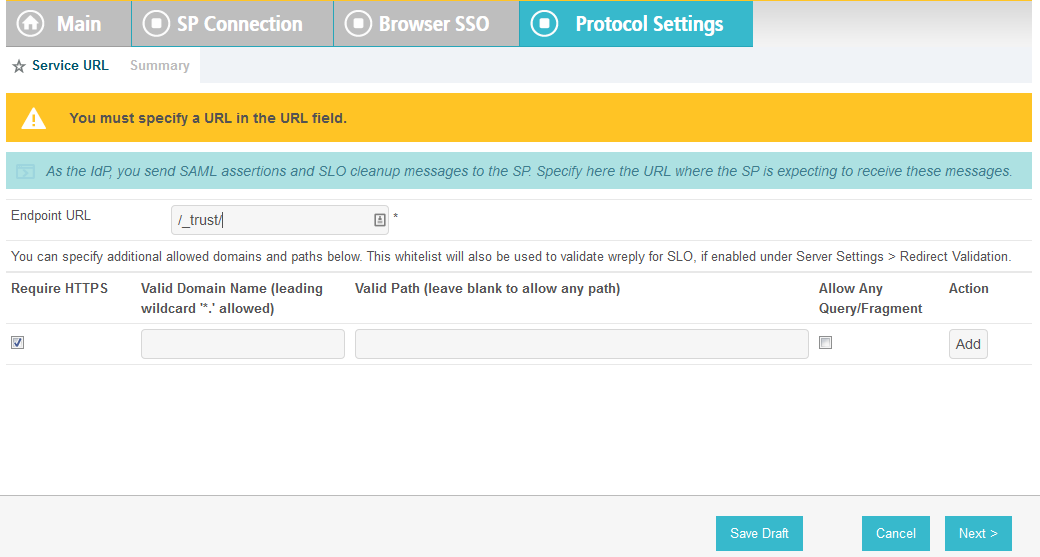
Click Next.
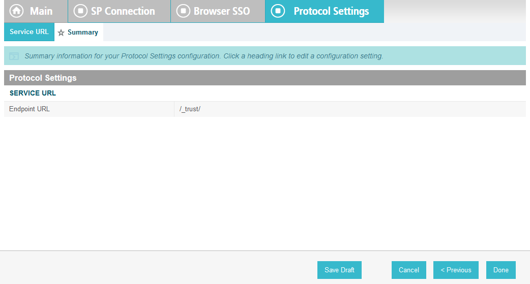
On the Summary screen, click Done.
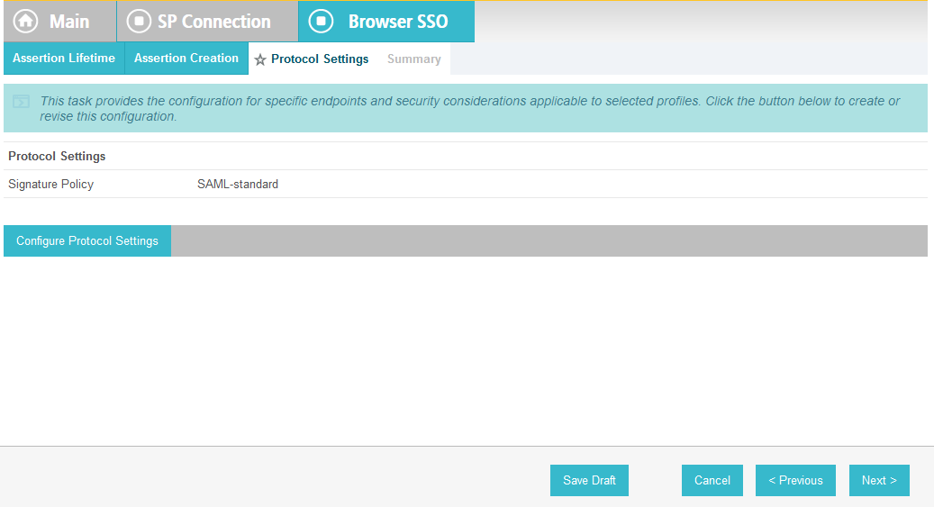
On the Protocol Settings screen, click Next.
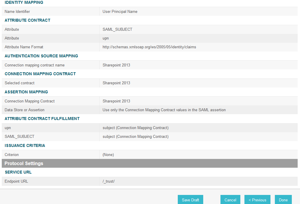
On the Summary screen, click Done.

On the Browser SSO screen, click Next.
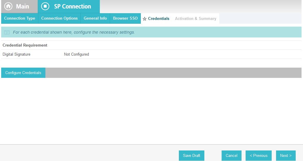
On the Credentials screen, click Configure Credentials. On the Digital Signature Settings screen, select the Signing Certificate for SAML messages.
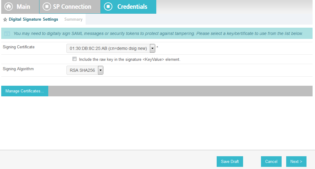
Click Next.
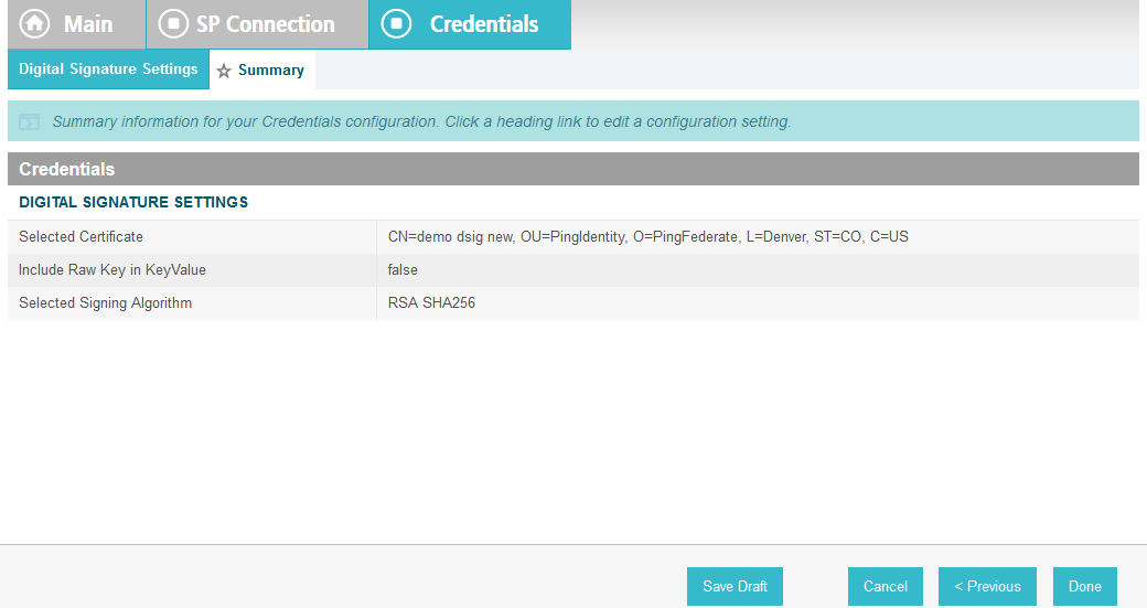
On the Summary screen, click Done.
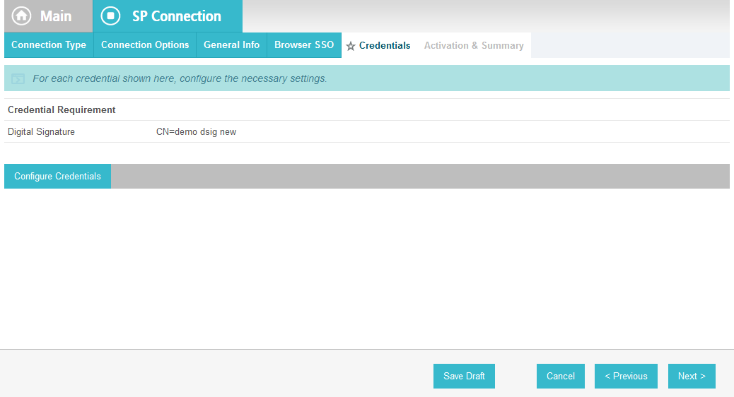
On the Credentials screen, click Next.

On the Activation and Summary screen, select Active for the Connection Status field and Click Save to complete the configuration.
5.5. Functional Test of All Configurations for Section 5
The instructions in this section will perform an integrated test all of the configurations in Section 5. Using the browser, you will logon using an account that was created in Active Directory and validate that the complete federated authentication flow between SharePoint and the PingFederate servers at the relying party and identity provider operates successfully.
Launch your Firebox browser and select SAML tracer from the Tools menu.
This will launch an empty SAML tracer window. Minimize the SAML tracer window. The SAML tracer will automatically record the details of the HTTPS messages in the background.
Go back to the main browser window and go to the relying party’s SharePoint site (e.g., https://SharePoint.abac.test).
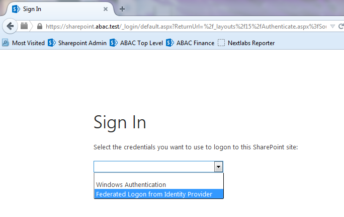
Select the option to use the new trusted token issuer (e.g., Federated Logon from Identity Provider) that was configured in this section.
Expected Result: Your browser should be redirected to the PingFederate-IdP and you should see the PingFederate Sign On screen. Examine the server name in the URL to ensure that it is the identity provider’s PingFederate server (e.g., idp.abac.test).
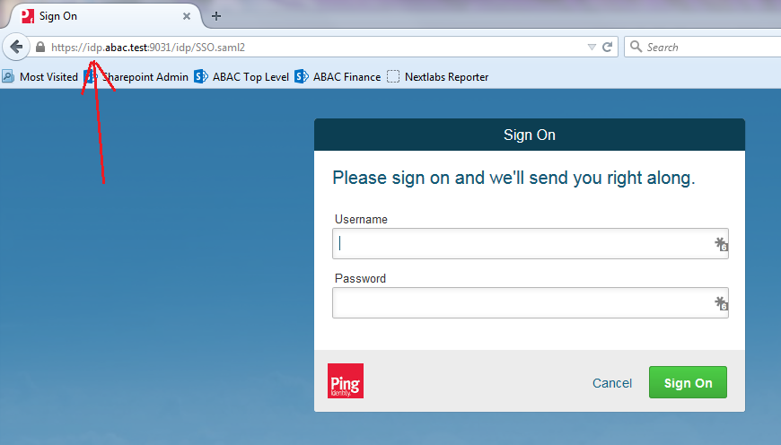
Enter the Username and Password of the Active Directory account created earlier in this guide (e.g., “lsmith”).
Click Sign On. On the RSA Adaptive Authentication screen, enter the SMS validation code received on your mobile phone. Click Next.
Note: Once authenticated at the identity provider, your browser should automatically redirect to the PingFederate-RP (e.g., rp.abac.test) and then to the relying party’s SharePoint (SharePoint.abac.test) site. Depending on the processing time of the servers in your environment, and other factors, it may take several seconds before your browser arrives back at the SharePoint site. The identity provider will redirect your browser to the PingFederate-RP first, and then the PingFederate-RP will redirect your browser to the SharePoint site, however you may not notice all of this activity if it happens quickly.
Expected Result: Go back to the SAML tracer window. Scroll down the list of messages at the top and ensure there is a POST message to the SharePoint server to the _trust URL (e.g., POST https://SharePoint.abac.test/_trust/).
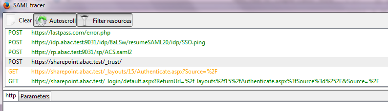
Click on the POST message to the SharePoint _trust URL to bring up the details of the message in the bottom pane.
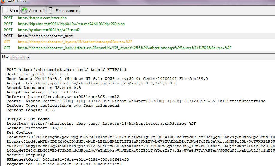
Click on the Parameters tab for the bottom pane.
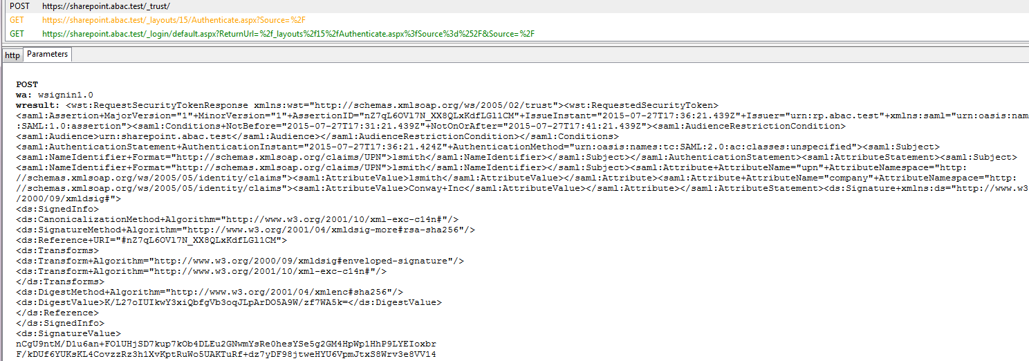
Copy all of the content (beginning with the POST line) in the bottom page and paste it into a text editor such as Notepad. Turn on Word Wrap to make it easier to see all of the XML content.

Scroll down the SAML message and locate the AttributeStatement node and sub-nodes.
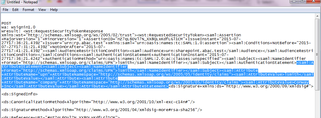
For the AttributeStatement node and sub-nodes, enter some carriage returns before each XML tag to make it easier to examine the data. The goal is to be able to easily examine the Attribute nodes within the AttributeStatement node.
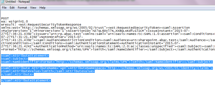
Expected Result: Within the AttributeStatement node, there should be an Attribute sub-node. The Attribute sub-node should have an AttributeName value of “upn”. The AttributeNamespace value should be http://schemas.xmlsoap.org/ws/2005/05/identity/claims. There should be an AttributeValue sub-node and it should contain the account username (e.g., “lsmith”) that was used to authenticate at the identity provider (e.g., <saml:AttributeValue>lsmith</saml:AttributeValue>).
Expected Result: Verify that the name (and case) of the attribute (noted by the AttributeName) is identical to the name configured at the SharePoint using Powershell earlier in this section. Verify that the AttributeNamespace is identical to the IncomingClaimType option configured at the SharePoint using Powershell earlier in this section. If the name or namespace of the attribute being passed to SharePoint does not match with the SharePoint configuration, SharePoint will not allow access to the site, and direct your browser back to the SharePoint Sign On screen.
If you verified that the name and namespace of the expected attribute match with the SharePoint configuration and SharePoint does not direct your browser to the site home page, follow the instructions in the Troubleshooting SharePoint Federated Authentication Problems section to determine the cause of the problem.
Expected Result: Go back to the main browser window. The SharePoint server should present the site home page. You should see the account username of the user that authenticated in the upper right corner of the page.
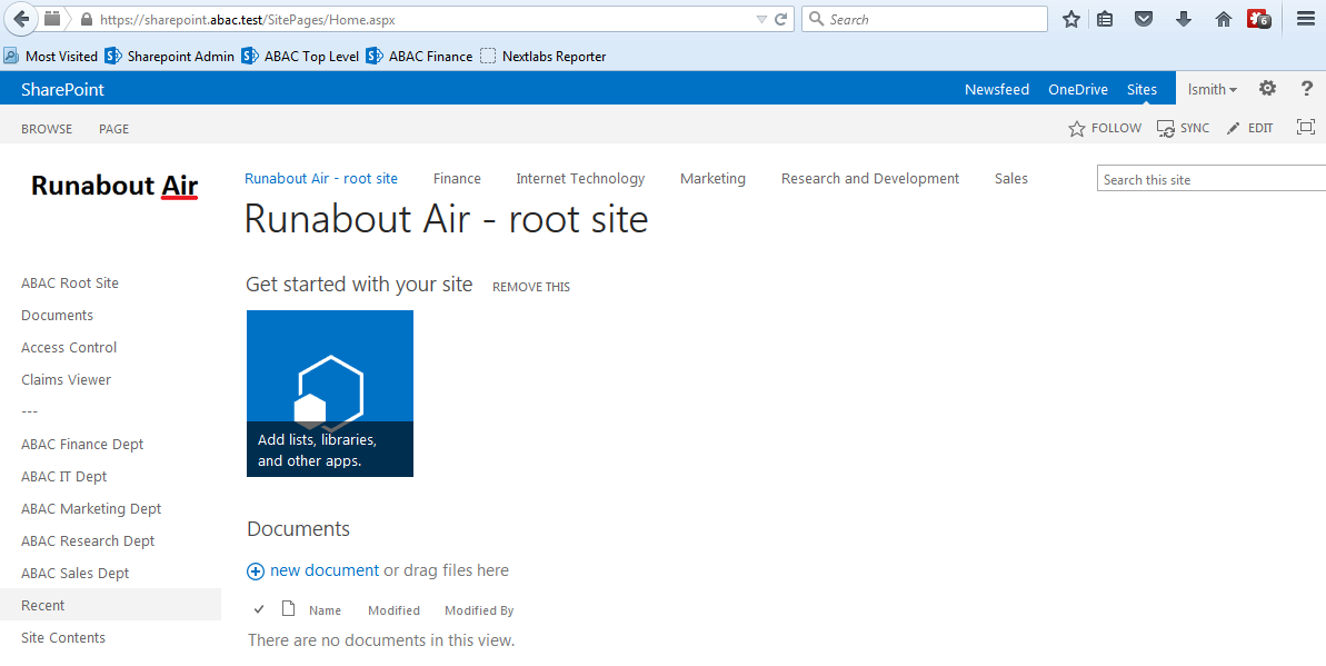
5.6. Troubleshooting SharePoint Federated Authentication Problems
If you encounter a situation where SharePoint is not allowing a federated user access to the site, you may have a problem with the authentication configuration. A symptom that indicates you have an authentication configuration problem is when a user successfully signs on at the identity provider, then the user is redirected back to the SharePoint site, and instead of displaying the site home page, SharePoint presents the SharePoint Sign On screen again. This section describes how to determine the root cause of this type of authentication problem so that the problem can be resolved.
Note: A SharePoint access control problem is a distinctly separate issue from authentication. A symptom of an access control problem is when the user received a message that states “This site has not been shared with you” upon successful authentication. Access control problems can be resolved by setting up SharePoint permissions on the People and Groups administration page, located in the Site Settings, Users and Permissions group.
Follow the instructions below to troubleshoot federated authentication problems at the SharePoint site.
Before you configure diagnostic logging for the SharePoint site to determine the root cause of the authentication problem, check the following items first:
Verify that the relying party’s PingFederate Server and the relying party’s SharePoint Server synchronize their clocks from the same source. If both servers are on the same domain, they should be synchronized with the domain controller automatically. Logon to both servers and verify that the clocks display the same time.
Verify that the expiration time of the security token generated by the PingFederate Server is more than 10 minutes. SharePoint calculates the time length of its session using the formula: SharePointSessionTime = SecurityTokenLifeTime – LogonTokenCacheExpirationWindow. SecurityTokenLifeTime is the length of time the token is valid, and this time is generated by the PingFederate server when it issues the token. By default the SharePoint LogonTokenCacheExpirationWindow is set to 10 minutes, therefore the SecurityTokenLifeTime must be greater than 10 in order to generate a SharePointSessionTime greater than zero. In our build we set the SecurityTokenLifetime to 20 minutes in the PingFederate configuration.
- The expiration time of the security token can be set in the configuration of the SP Connection on the relying party’s PingFederate server. When you open the configuration for the SP Connection, click on the Assertion Lifetime link in the Browser SSO section. Enter a value for the Minutes After field that is greater than 10 (e.g., 20).
If you checked the items in the previous section and you are still encountering authentication problems, you will need to examine detailed authentication logs on the SharePoint server. Follow the instructions below to configure diagnostic logging on the SharePoint server and analyze the logs to determine the root of the authentication problem.
Perform the instructions at the link below to change the levels of ULS authentication logging on the SharePoint server. Make sure that you perform the instructions in the following two sections of the article:
- “To configure SharePoint 2013 for the maximum amount of user authentication logging”
- “To find the failed authentication attempt manually” https://technet.microsoft.com/en-us/library/JJ906556.aspx
Once you configure the SharePoint diagnostic authentication logging, perform the sign on process to your SharePoint again to generate activity in the log.
Since the SharePoint ULS log file contains many entries, it can be helpful to copy the file to another computer and analyze it offline.
Open a copy of the log file and scroll to the bottom of the file. The bottom of the log contains the most recent activity.
Starting at the bottom of the file, perform an upward search for the term “authentication”. Examine the entries that are labeled either “Claims Authentication” or “Authentication Authorization”.
Look at the details for each of these two types of authentication entries to look for clues regarding what the source of the problem could be. You may have to look through several entries in the file to understand the sequence of events.
We used this approach to troubleshoot an authentication problem in our lab. We found the following entry in the log file, that seemed as though it could be the source of the problem:
- security token ‘0e.t|federated logon from identity provider|lsmithcc221cd9-23d7-4302-b029-ee81784754d2_Internet’ is found in the local cache, but it is expired. Returing Null.
Two lines further down in the file, we found the following entry as well:
- token cache: Failed to find token for user ‘0e.t|federated logon from identity provider|lsmith’ for cookie so signing out the user
Based on the log file, we performed an Internet search for the term “security token is found in the local cache, but it is expired. Returing Null”. By researching various Internet blogs and forums, and performing additional analysis of the log file, we found a blog article on the PingIdentity website that described why the lifetime of the security token generated by the PingFederate-RP must be greater than 10 minutes when issuing a token for SharePoint. Once we updated the associated configuration on the PingFederate-RP, the authentication problem was resolved.
6. Attribute Exchange between the Identity Provider and Relying Party
6.1. Introduction
In previous sections of this How-To Guide, we demonstrated foundational steps to building an ABAC solution:
- configuring federated authentication at the PingFederate-IdP
- configuring the SAML exchange between the PingFederate-IdP and PingFederate-RP
- configuring the Relying Party’s SharePoint site
- configuring the federated logon at the SharePoint site
Building upon that foundation, this section describes how to:
- create custom attributes and set values for them in Microsoft AD
- configure the PingFederate-IdP to pull user and environmental attributes during authentication
- configure the PingFederate-RP to pass the user and environmental attributes to the RP’s SharePoint
- configure SharePoint to load the user and environmental attributes passed from the PingFederate-RP into the web session
If you follow the instructions in this How-To Guide section, you will be able to perform a Functional Test to verify the successful completion of the steps for installing, configuring, and integrating the components.
6.2. Create Custom User Attributes in Microsoft AD
Follow the instructions in this section to create custom user attributes in the Microsoft AD schema. You will add a new attribute and add it to the “user” class. Microsoft AD user accounts inherit from the “user” class; therefore, the new attribute will be available to all of the users in the domain.
6.2.1. Preparing the AD Schema for Creating New Custom Attributes
6.2.1.1. Backing Up Your Directory before Making Schema Changes
Microsoft recommends that you back up your directory before making schema changes. Choose the names of your new custom attributes carefully, because the creation of a new attribute is a permanent operation.
Log on to the server that contains the Microsoft AD schema (typically the schema is on the domain controller).
Launch a Command Prompt, using the Run as Administrator option.
Execute the following command: regsvr32 schmmgmt.dll
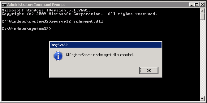
Click the Start button and enter mmc.exe in the search field.
Launch the mmc.exe program.
Click on the File menu. Then, click Add / Remove Snap-in.
Click on Active Directory Schema in the list of Available snap-ins on the left; then, click Add to add it to the Selected snap-ins on the right.
Click OK.
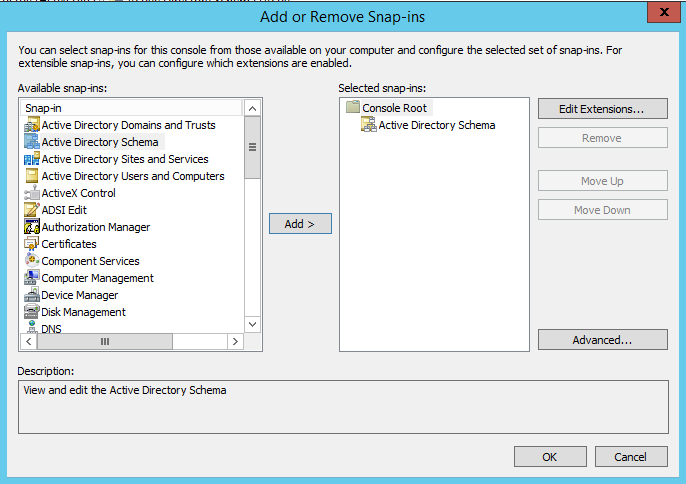
Expand the Active Directory Schema on the left.
6.2.1.2. Reviewing Existing Attributes to Avoid Redundancies when Creating New Attributes
Before you create a new attribute, it is important to review existing user attributes in your Active Directory Schema. Under Active Directory Schema on the left, expand the Classes folder and scroll down to click on the user class. Examine the existing set of user class attributes listed on the right. These attributes are native to Active Directory, and can be assigned to users as subject attributes. These attributes may meet existing requirements for implementing subject attribute, alleviating the need to add custom attributes to the schema. You can list the attributes in alphabetical order by clicking on the Name column.
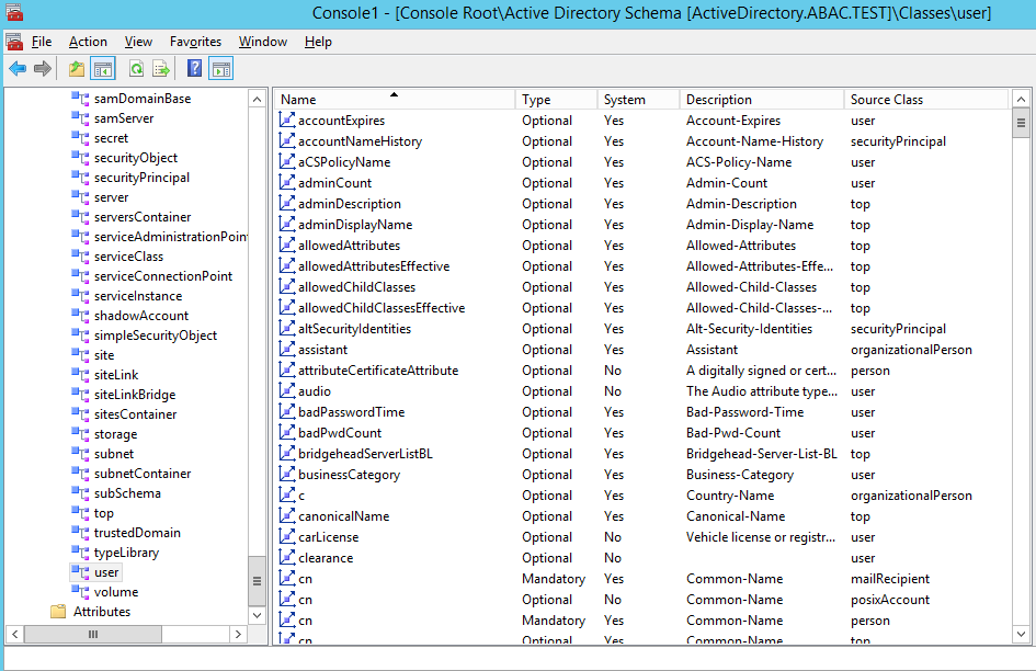
If you wanted to create an attribute to store the user’s cell phone number, you would look through the attributes and notice that the attribute cellphone does not exist. However, there is an attribute named mobile that could be used to store a cell phone number.
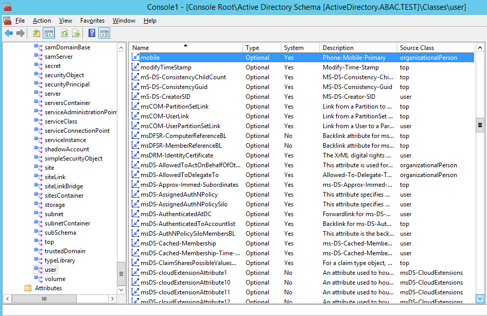
Once you have identified that the creation of a new attribute is warranted, proceed with the following instructions.
6.2.1.3. Creating New Custom Attributes
Launch a browser window and go the Microsoft site: https://gallery.technet.microsoft.com/scriptcenter/56b78004-40d0-41cf-b95e-6e795b2e8a06
Copy the oidgen.vbs script code that is shown on the page to the clipboard.
Open Notepad and paste the script into the editor.
Save the script to a file on the desktop named oidgen.vbs.
Go back to the Active Directory schema window.
On the left pane, click on the Attributes folder.
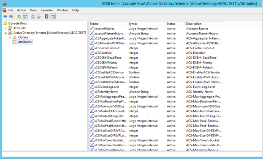
Right-click on the Attributes folder and select Create Attribute.
Click Continue on the warning window.
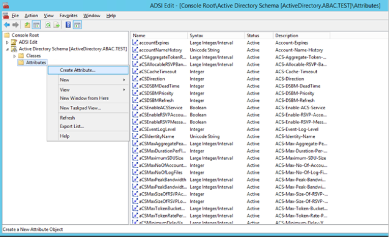
Enter the name of your new attribute and select the type of attribute in the Syntax field. In the example below, the name of the new attribute is clearance and the type of attribute is Unicode String.
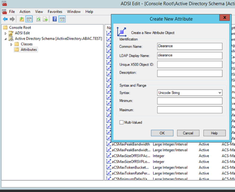
6.2.1.4. Generating an ID to Enter into the Unique X500 Object ID Field
Next, you need to generate an ID to enter into the Unique X500 Object ID field.
Go to the desktop and double-click on the oidgen.vbs script that was saved earlier. This should execute the script to generate a unique Object ID.
Enter this long Object ID into the Unique X500 Object ID field in the Active Directory Create New Attribute window.
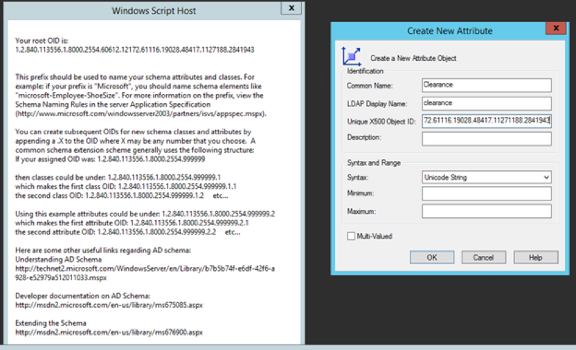
Click OK to create the new attribute.
Scroll down the list of attributes and make sure your newly added attribute is listed there.
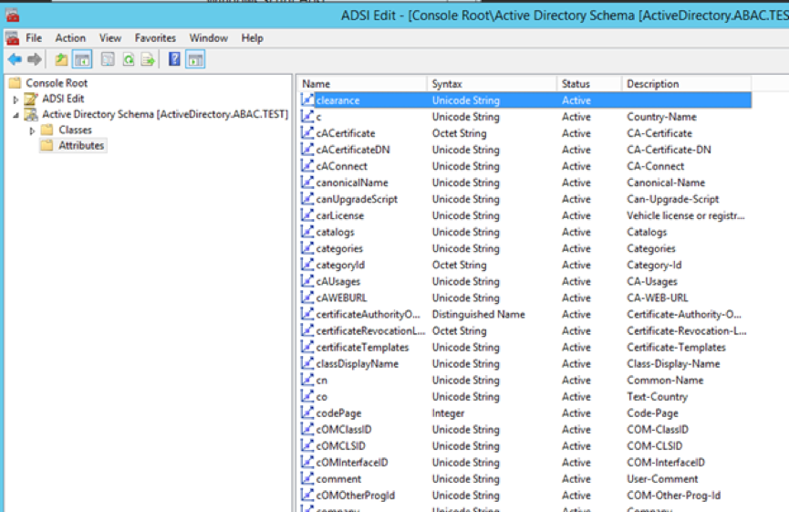
6.2.1.5. Adding the New Attribute to the User Class
Next, you need to add the new attribute to the user class.
In the left pane, expand the Classes folder. Scroll down the list of classes, right-click on the user class, and select Properties.
Click on the Attributes tab.
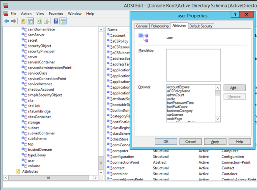
Click Add. Scroll down and click on the new attribute.
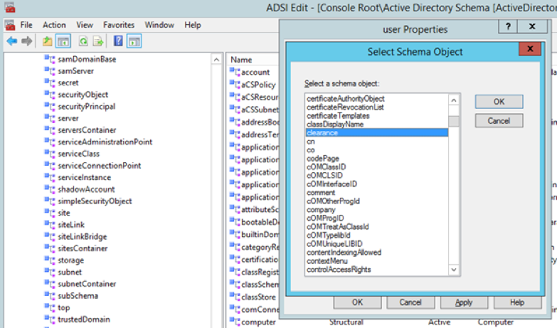
Click OK on the Select Schema Object window, and then click OK one more time on the user properties window. At this point, you have added the new attribute to the user class.
When you examine the list of attributes for the user class, you should be able to see the new attribute.
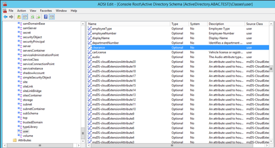
6.2.2. Set Values for Custom User Attributes in Microsoft AD
Once you have created a new custom attribute in the Active Directory user class, that new attribute will be available for all users in the domain. You will be able to set specific values for the new attribute for each distinct user. Follow the instructions in this section to set a user-specific value for a new attribute in Active Directory.
Log on to the Microsoft AD server.
Open the Active Directory Users and Computers program.
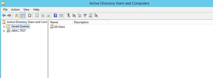
Click on the View menu and select Advanced Features.
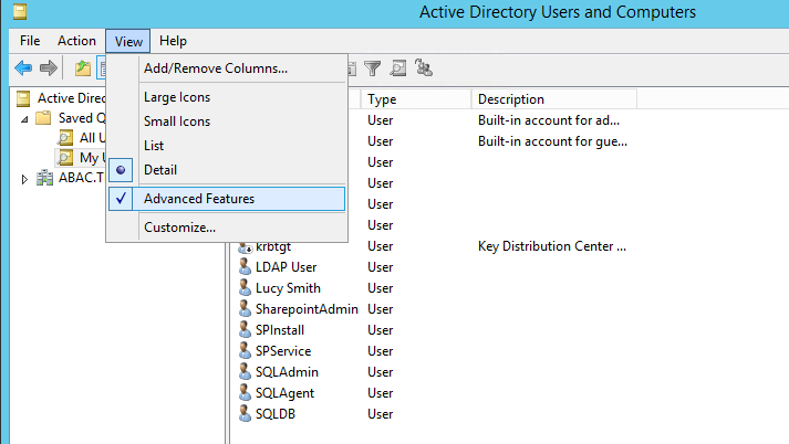
Right-click on Saved Queries and select New > Query. Enter a name for your query (e.g., My Users).
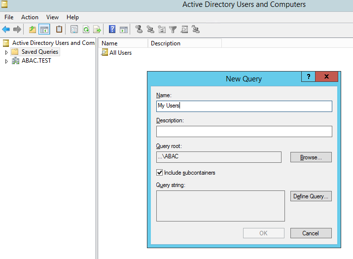
Click on Define Query. From the Name list, select Has a value.
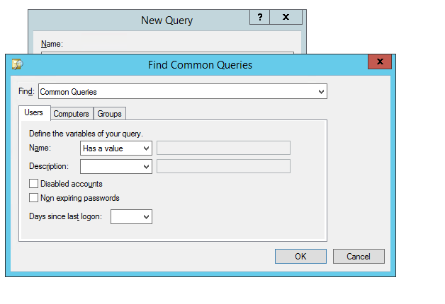
Click OK. Then, click OK again to create your new query.
You will see a list of Active Directory Users displayed in the right pane.
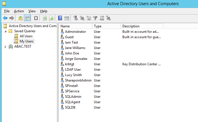
Double-click on the specific user (e.g., Lucy Smith) that you want to modify to bring up the properties window.
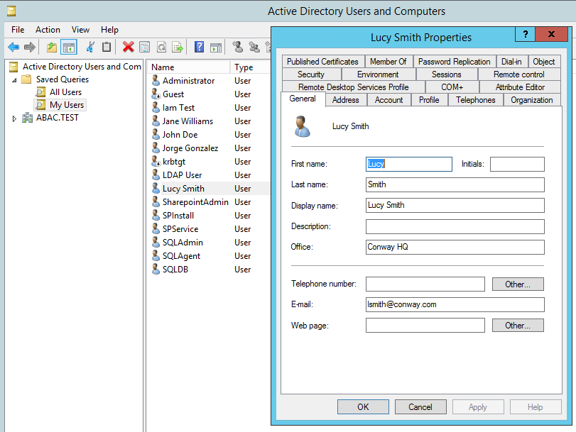
Click on the Attribute Editor tab.
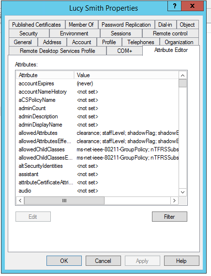
Scroll down and locate the new custom attribute for which you want to set a value (e.g., clearance).
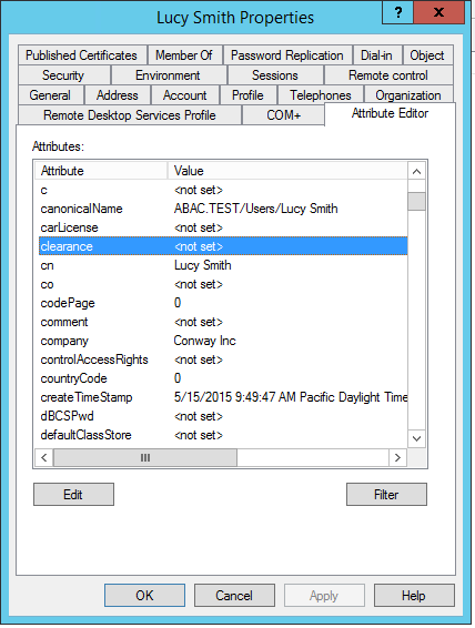
Double-click on the attribute, and enter a value suitable for your organization. In this example, the clearance attribute will be set to a value of Interim for the user Lucy Smith in subsequent steps.
Click OK and then click OK again. The information is saved and the User Properties window closes.
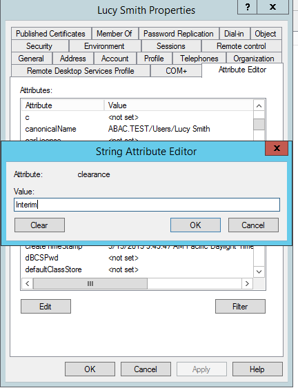
Note: When you set an attribute value in the attribute editor and then go back to the Users query view, you have to press F5 or click the Action menu > Refresh to see the new value.
6.2.2.1. Adding New Columns to the Users Query View
Next you will add new columns to the Users query view to help monitor the custom attribute values for each user in the directory. By default, the Users view only shows the attribute values for Name, Type, and Description.
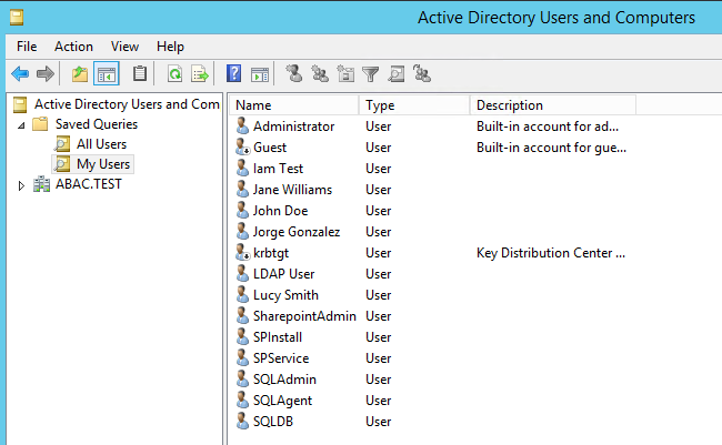
- In the Saved Queries folder, click on the name of the query to be modified (e.g., My Users).
- Click on the View menu and select Add/Remove Columns…
- From the list of Available columns, scroll up or down to find desired columns.
- Click on column name and click on the Add button.
- When all desired columns have been chosen, click OK.
The following screenshot shows a query view after adding custom attribute columns. The example contains new columns for the attributes User Logon Name, Company, Department, Title, Staff Level, and Clearance.
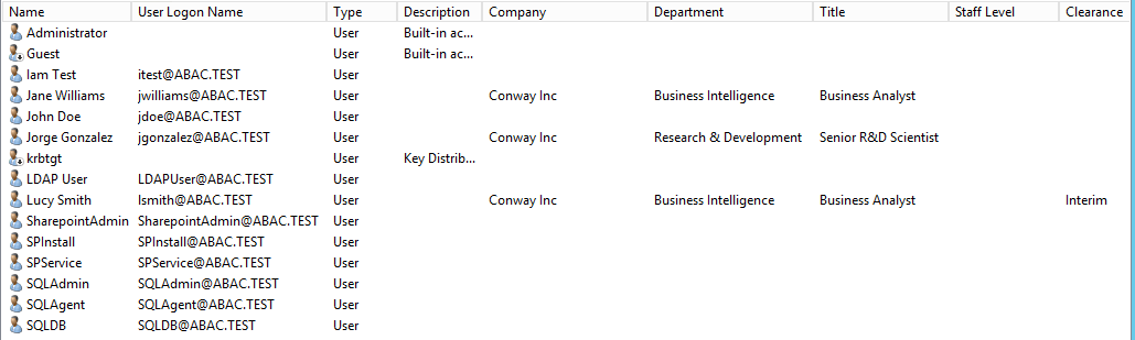
6.3. Configure PingFederate Servers to Pull User Attributes
6.3.1. Configure PingFederate-IdP to Pull User Attributes During Authentication
Follow the instructions in this section to configure the PingFederate-IdP to pull user attribute values from Microsoft AD and Cisco ISE during the authentication process. In the following example, the value for the user attribute company is extracted from Microsoft AD.
Launch your browser and go to https://<DNS_NAME>:9999/pingfederate/app.
Replace DNS_NAME with the fully qualified name of the IdP’s PingFederate server (e.g., https://idp.abac.test:9999/pingfederate/app).
Log on to the PingFederate application using the credentials you configured during installation.
On the Main Menu under SP CONNECTION, click Manage All SP.
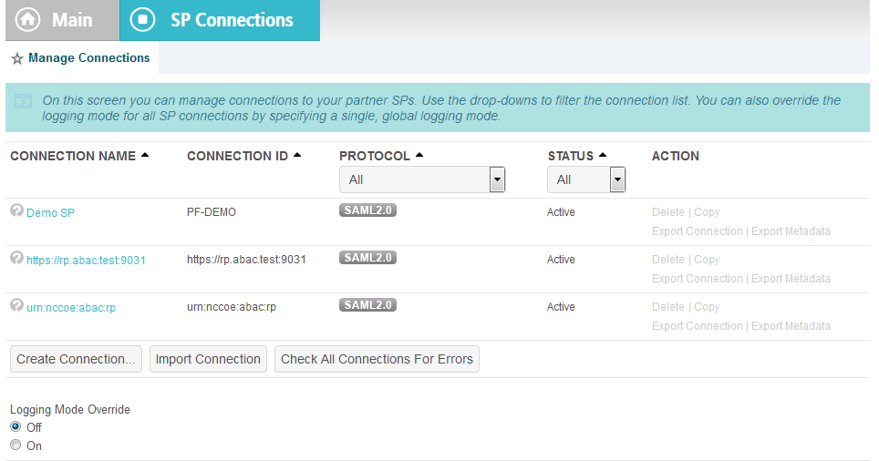
Click on the link for the connection created in Section 3 (e.g., https://rp.abac.test:9031).
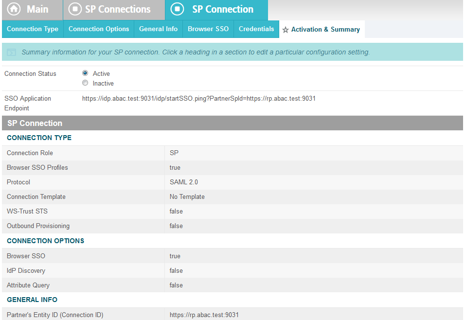
On the Activation & Summary screen, scroll down to the Assertion Creation group and click on the ATTRIBUTE CONTRACT link.
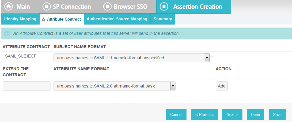
On the Attribute Contract screen, under the EXTEND THE CONTRACT column, enter the name of the attributes to be extracted from Microsoft AD, Cisco ISE, and RSA AA (e.g., company) in the empty text field.
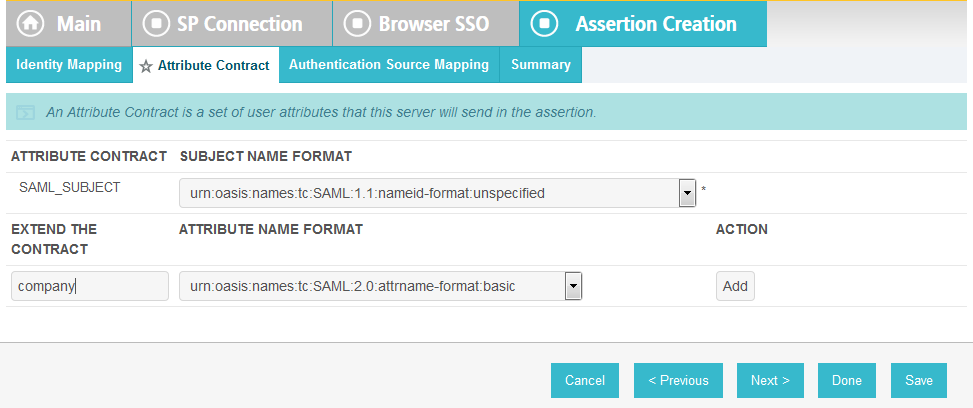
Click Add.
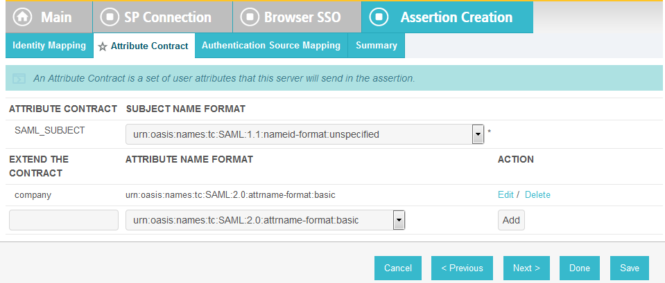
Click Save to complete the configuration.
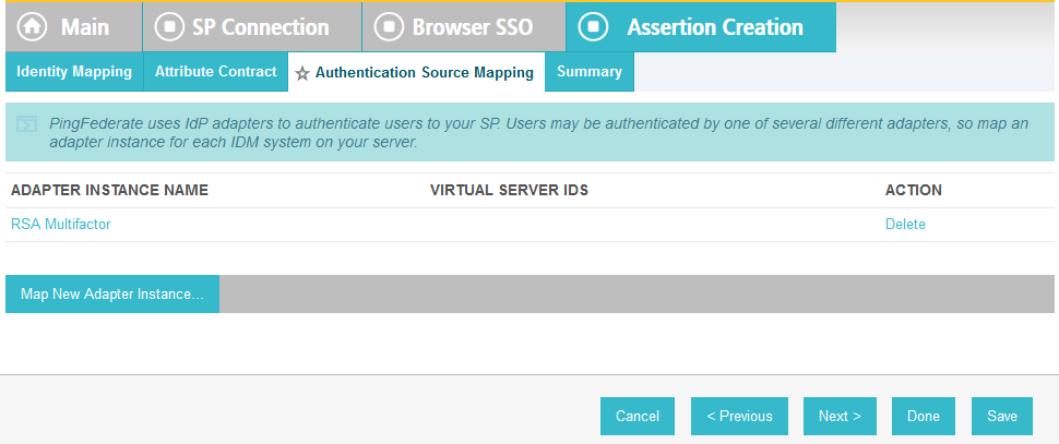
6.3.1.1. Functional Test of Pulling User Attributes During Authentication
The instructions in this section will help you perform a test to ensure that the Identity Provider is getting the configured attributes (e.g., company) from Active Directory and passing them in a SAML message to the RP. The Firefox SAML tracer add-on is used to examine the SAML message.
Follow the instructions in the section Temporarily Disable SAML Encryption for Testing and Troubleshooting Message Exchanges at the end of this section to disable SAML encryption. Once SAML encryption has been disabled, you can proceed with the following functional test instructions.
Launch your Firebox browser and select SAML tracer from the Tools menu. This launches an empty SAML tracer window.
Minimize the SAML tracer window.
The SAML tracer automatically records the details of the HTTPS messages in the background.
Go back to the main browser window and go to the RP’s SharePoint site (e.g., https://SharePoint.abac.test).
Select Federated Logon from Identity Provider.
In the Identity Provider’s PingFederate Sign On screen, enter the credentials for the account you are testing with (e.g., lsmith) and click Sign On.
On the RSA two-factor authentication screen, enter the validation code and proceed. The browser redirects you to the PingFederate-RP and then to the RP’s SharePoint site. You may not notice the redirection to the PingFederate-RP if it happens quickly.
Go back to the SAML tracer window. Scroll down and click on the last POST message that contains a SAML icon.
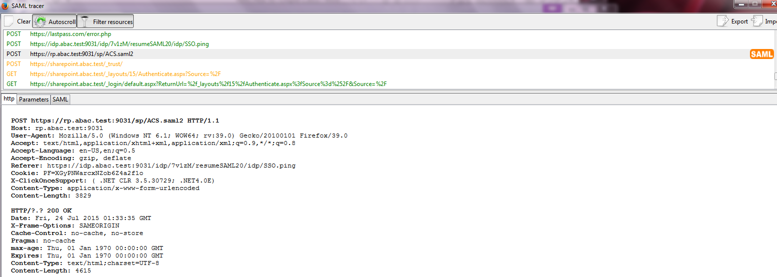
Click on the SAML tab. Scroll down the SAML message and locate the AttributeStatement node and sub nodes.
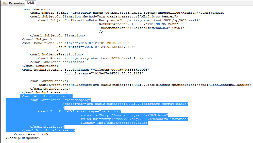
Expected Result: Ensure that the attribute you configured from Microsoft AD contains a node. In the example screenshot above, you can see that there is an Attribute node for the company attribute because of the line <saml:Attribute Name= “company”.
Expected Result: Ensure that the AttributeValue node contains the expected value for the attribute from ActiveDirectory. In the example screenshot above, you can see there is an AttributeValue node for the company attribute and the value is Conway Inc. This is correct, because in our Microsoft AD environment, the user account we tested with is lsmith (Lucy Smith), and Lucy’s company attribute in Microsoft AD is set to a value of Conway Inc.
When you complete this functional test, you must enable SAML encryption between the IdP and RP again. Follow the instructions in the section Temporarily Disable SAML Encryption for Testing and Troubleshooting Message Exchanges, subsection Enable SAML Encryption at the end of this section again to enable SAML encryption.
6.3.2. Configure PingFederate-IdP to Pull Environmental Attributes During Authentication
Follow the instructions in this section to configure the PingFederate-IdP to get environmental attribute values from the RSA Adaptive Authentication system during the authentication process. The environmental attributes are passed along with the user attributes in the SAML messages that is sent to the RP. In the example below, the environmental attribute ip_address will be pulled from RSA Adaptive Authentication.
RSA Adaptive Authentication stores environmental attributes about the user’s web transactions in a SQL Server database named RSA_CORE_AA. The PingFederate-IdP will be configured to query to the RSA_CORE_AA database and get the value of ip_address from the EVENT_LOG table.
Before you can configure the query for ip_address, you must first create an account for the PingFederate application in the RSA_CORE_AA database. Follow the instructions below to create the account in the SQL Server database.
Log on to the server that hosts the RSA Adaptive Authentication SQL Server database engine.
Open SQL Server Management Studio.
Expand the RSA-AA-Server folder, then the Security folder.
Right-click on Logins and select New Login.
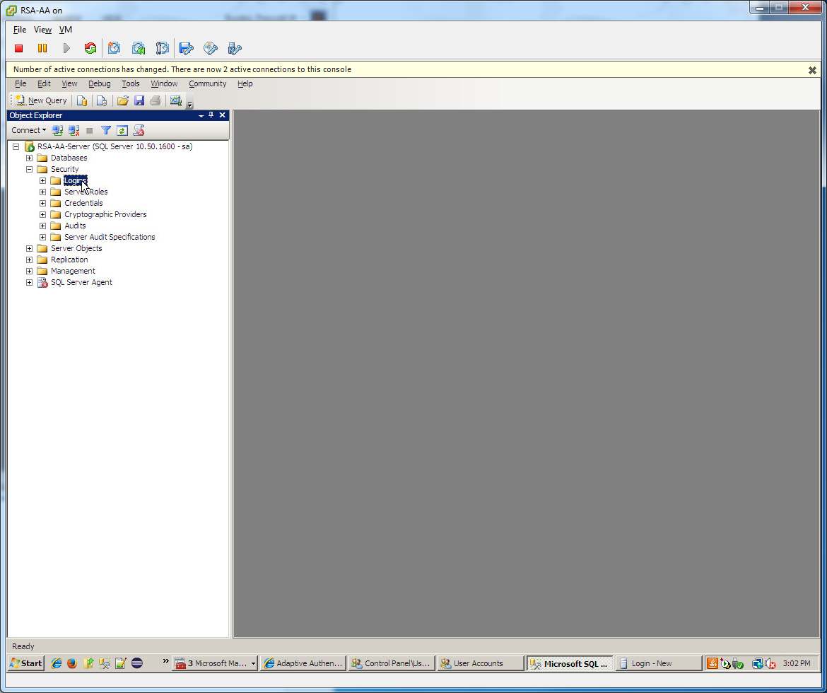
Set the Login name (e.g., ping), under SQL Server authentication and choose a password that meets the Windows password policy.
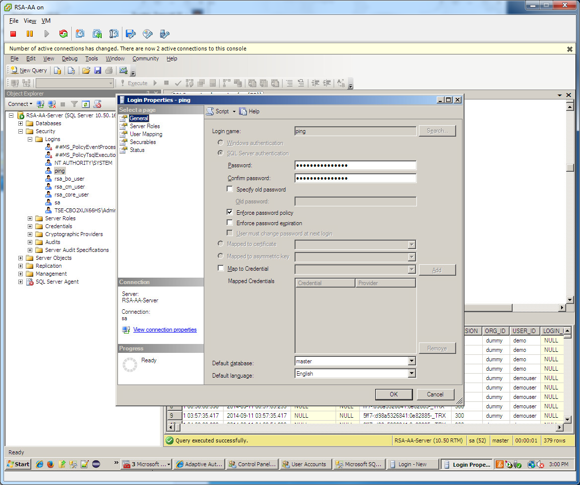
Under Server Roles, select public.
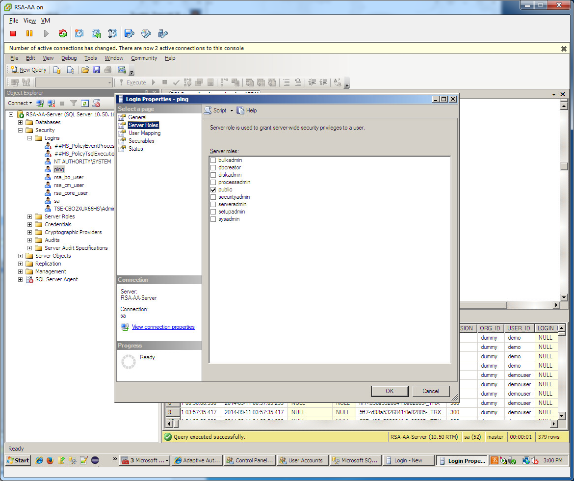
Under User Mapping, check the Map box next to RSA_CORE_AA. In the bottom pane, under Database role membership, check the box next to db_datareader.

Under Status, set permission to connect to database engine to Grant and Login to Enabled. Click OK.
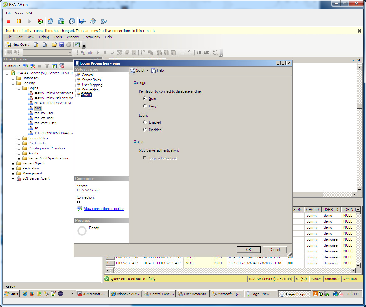
6.3.2.1. Configuring a New Data Store that Connects to the RSA database
Next, you will configure a new Data Store that connects to the RSA_CORE_AA database on the Identity Provider’s PingFederate server. This new data store will be used in the RP Connection to query the EVENT_LOG table during the authentication process.
Follow the instructions below to create a new Data Store for the RSA_CORE_AA database.
Launch your browser and go to https://<DNS_NAME>:9999/pingfederate/app. Replace <DNS_NAME> with the fully qualified name of the IdP’s PingFederate server (e.g., https://idp.abac.test:9999/pingfederate/app).
Log on to the PingFederate application using the credentials you configured during installation.
Under Server configuration, select Data Stores.

Under Manage data stores, select Add new data store. Select Database as type of data store. Click Next.
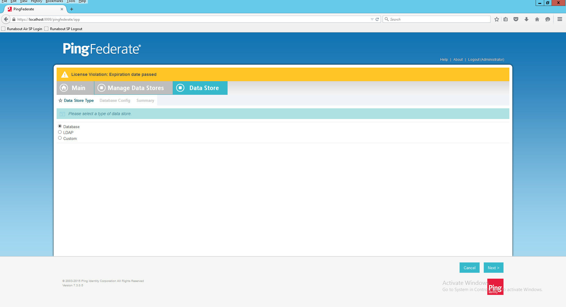
On the database config page, set the JDBC URL to: jdbc:sqlserver://<RSA_SERVER_IP_ADDRESS>:1433;databaseName=RSA_CORE_AA
- Replace <RSA_SERVER_IP_ADDRESS > with the IP address of the server that hosts the RSA_CORE_AA database.
Set the driver class to com.microsoft.sqlserver.jdbc.SQLServerDriver
In the Username and Password fields, enter the credentials for the Ping user created in the SQL server RSA Database.
Under Validate Connection SQL, type SELECT 1=1.
Check the box to allow multi-value attributes. Click Next.
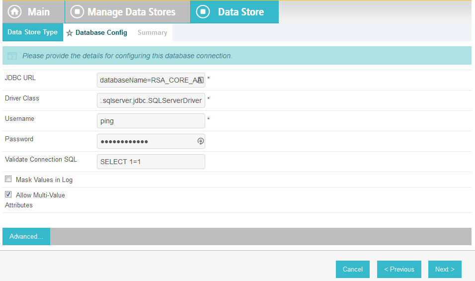
Review the settings on the summary page. Then, click Save.

6.3.2.2. Modifying the SP Connection to the RP to Add New Environmental Attribute
Next, you will modify the SP Connection to the RP and add a new environmental attribute, ip_address, from the RSA_CORE_AA database.
Go to the PingFederate main menu. On the Main menu under SP CONNECTION, click Manage All SP.
Click on the link for the SP connection created in Section 2 (e.g., https://rp.abac.test:9031).
On the Activation & Summary screen, scroll down to the Assertion Creation group and click on the ATTRIBUTE CONTRACT link.
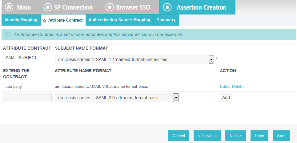
On the Attribute Contract screen, under the EXTEND THE CONTRACT column, enter the name of the environmental attribute to be pulled from the RSA_CORE_AA database (e.g., ip_address) in the empty text field.
Click Add.
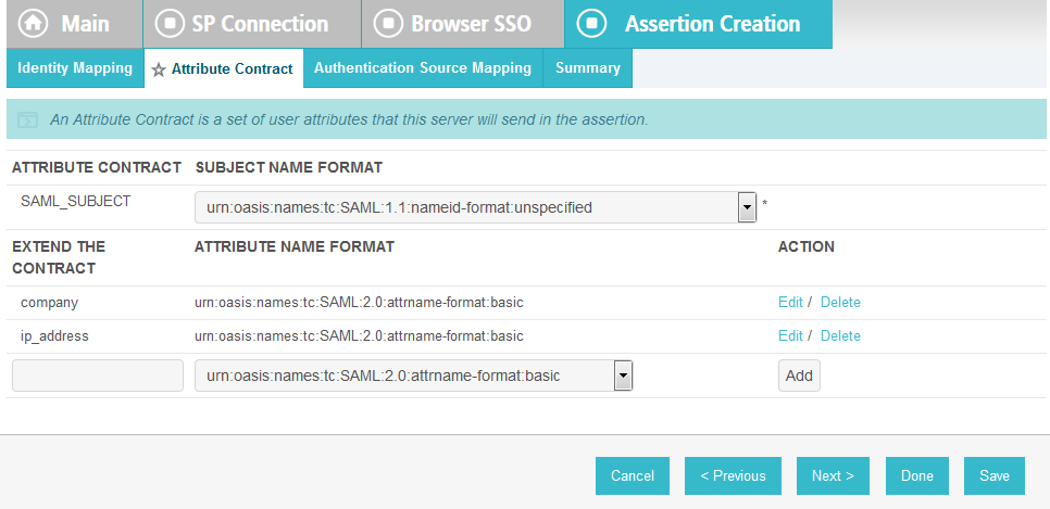
Click Next.
On the Authentication Source Mapping screen, click on the name of the ADAPTER INSTANCE (e.g., RSA Multifactor).
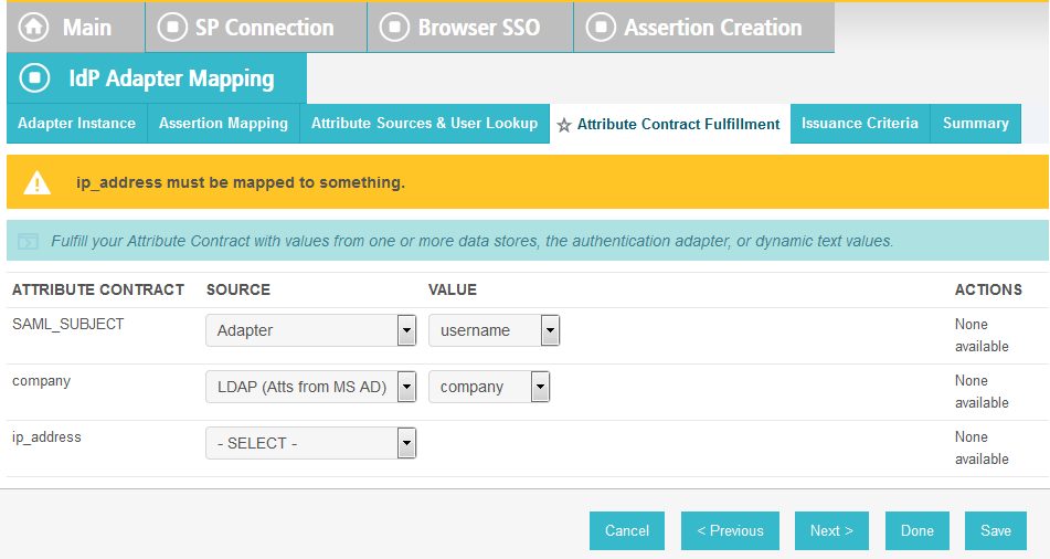
Click on the Attribute Sources & User Lookup tab.
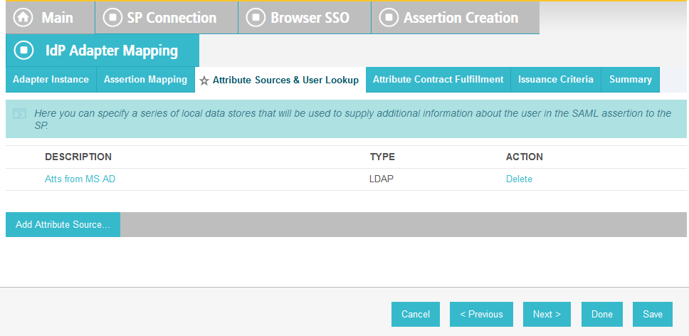
Click Add Attribute Source.
On the Attribute Sources & User Lookup screen, enter a unique name in the Attribute Source Id field (e.g., RSAEventLog).
Enter a description (e.g., Atts from RSA).
For the Active Data Store field, select the existing Data Store that connects to the RSA_CORE_AA database.
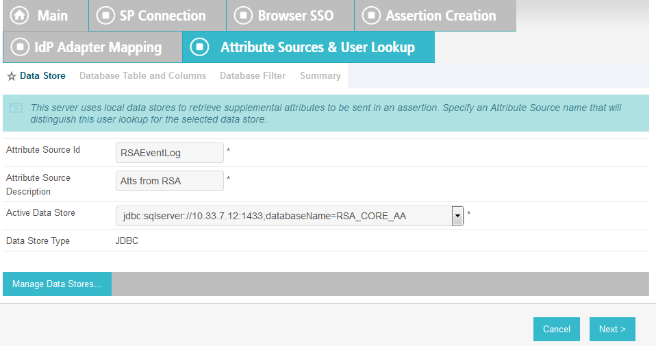
Click Next.
On the Database Table and Columns screen, select the dbo Schema.
Select the EVENT_LOG table.
Under the Columns to return from SELECT, select the IP_ADDRESS column and click Add Attribute.
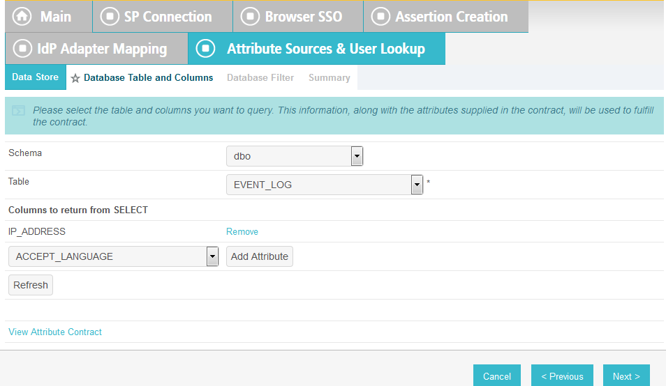
Click Next.
On the Database Filter screen, enter the text on the following line into the text field for the Where. Make sure to include the quotes.
EVENT_ID = ‘${transactionid}’
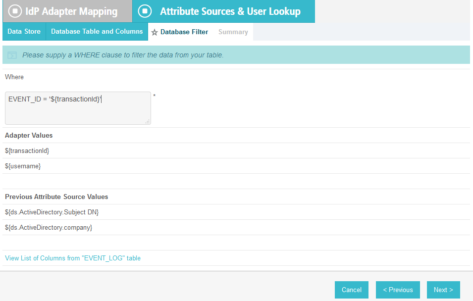
Click Next.
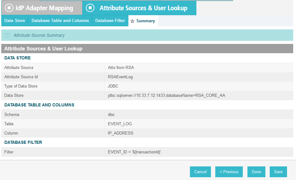
On the Summary screen, click Done.
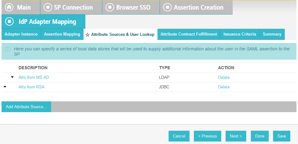
On the Attribute Sources & User Lookup screen, click Done.
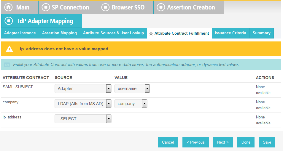
On the Attribute Contract Fulfillment screen, for the ip_address attribute, select the SOURCE and VALUE. For the SOURCE, select JDBC (Atts from RSA). For VALUE, select IP_ADDRESS.
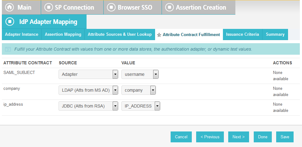
Click Save to complete the configuration.
6.3.2.3. Functional Test of Pulling Environmental Attributes during Authentication
To test that the Identity Provider’s PingFederate server is successfully getting the environmental attributes during the authentication process, follow the instructions in the section Functional Test of Pulling User Attributes during Authentication. The only exception to those instructions is that when you examine the SAML message, you need to look for the environmental attribute that is being pulled from the RSA_CORE_AA database. See below for an example.
Once you have the message open in the SAML tracer window, scroll down the message and locate the AttributeStatement node and sub-nodes.
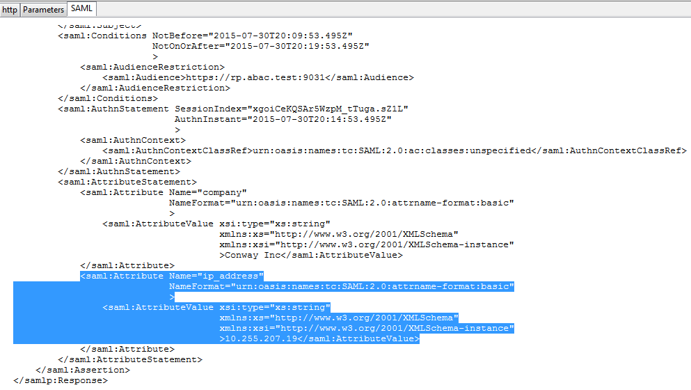
Expected Result: Ensure that the attribute you configured to be pulled from the RSA_CORE_AA database contains a node. In the example screenshot above, you can see that there is an Attribute node for the ip_address attribute because of the line <saml:Attribute Name=“ip_address”.
Expected Result: Ensure that the AttributeValue node contains the expected value for the attribute from the RSA_CORE_AA database. In the example screenshot above, you can see that there is an AttributeValue node for the ip_address attribute, and the value is 10.255.207.19.
6.3.3. Configure PingFederate-RP to Pull Attributes from the Identity Provider’s SAML Exchange
Once the PingFederate-IdP completes the authentication for a user, the IdP will send a SAML message to the PingFederate-RP. That SAML message will contain attributes.
Follow the instructions below to configure the PingFederate-RP to get attributes and their associated values from the SAML message exchange with the IdP. In the example below, the attribute being configured at the RP is the company attribute.
Launch your browser and go to https://<DNS_NAME>:9999/pingfederate/app. Replace DNS_NAME with the fully qualified name of the Relying Party’s PingFederate server (e.g., https://rp.abac.test:9999/pingfederate/app). Log on to the PingFederate application using the credentials you configured during installation.
On the main menu, under IDP CONNECTIONS, click on the connection that was configured to the IdP in Section 3 (e.g., https://idp.abac.test:9031).
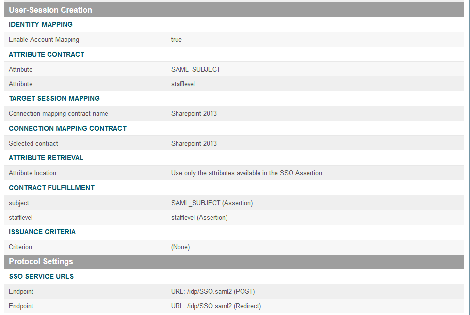
On the Activation & Summary screen, scroll down to the User-Session Creation group and click on the ATTRIBUTE CONTRACT link.
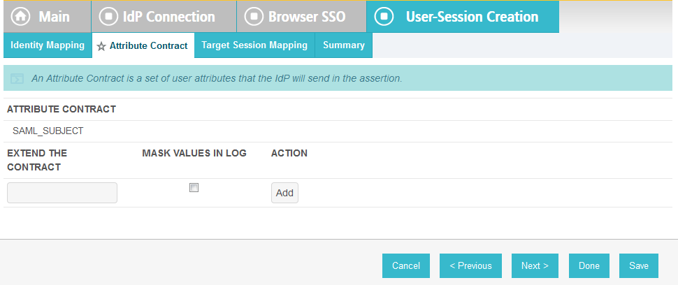
On the Attribute Contract screen, under the EXTEND THE CONTRACT column, enter the name of the attribute to be pulled from the IdP’s message (e.g., company) in the empty text field. In the ACTION column, click Add.
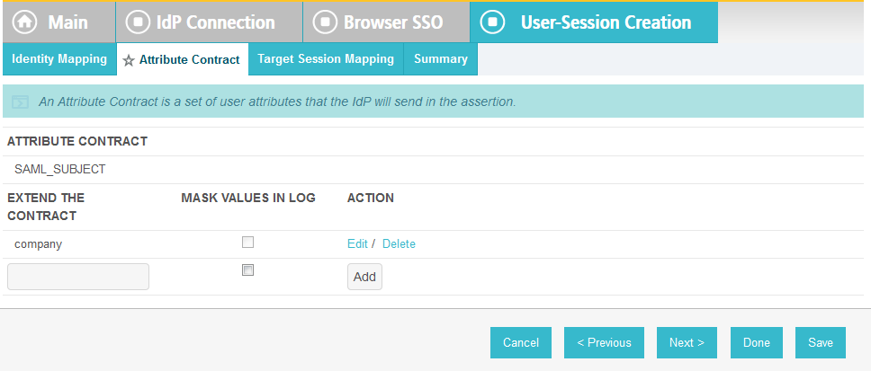
Click Done.
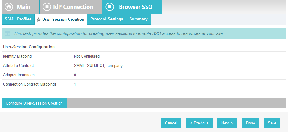
On the User-Session Creation screen, click Configure User-Session Creation.

On the Summary page, under User-Session Creation, click on the CONNECTION MAPPING CONTRACT link.
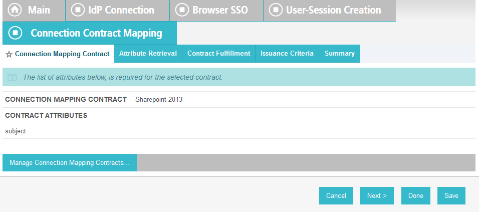
On the Connection Mapping Contract screen, make note of the CONNECTION MAPPING CONTRACT being used, because you will need to modify it by adding new attributes. In the example screenshots, the contract name is SharePoint 2013.
Click on Manage Connection Mapping Contracts.

On the Manage Contracts screen, click on the name of the contract that is being used for the current configuration (e.g., SharePoint 2013).

On the Summary screen, click on the Contract Attributes link.
On the Contract attributes screen, under the EXTEND THE CONTRACT column, enter the name of the attribute to be shared with the PingFederate service provider connection (e.g., company).
In the ACTION column, click Add.
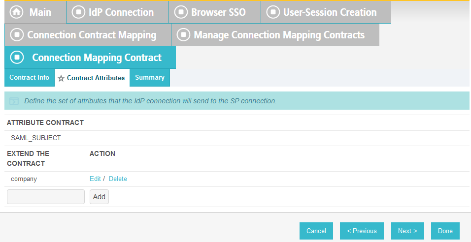
Click Done.
On the Manage Contracts screen, click Save.
On the Connection Mapping Contract screen, you should see the new attribute (e.g., company) listed on the page.
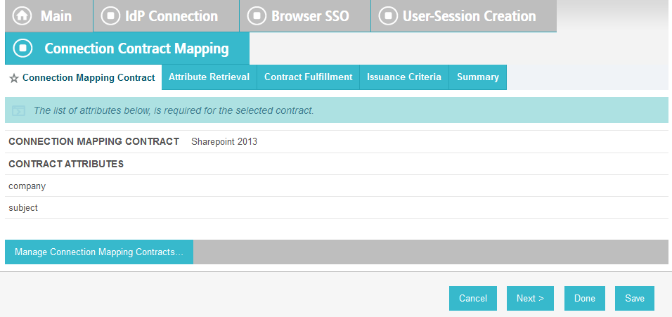
Click on the Contract Fulfillment tab.

On the Contract Fulfillment screen, for the new attribute (e.g., company), select Assertion for the SOURCE field and select company for the VALUE field.
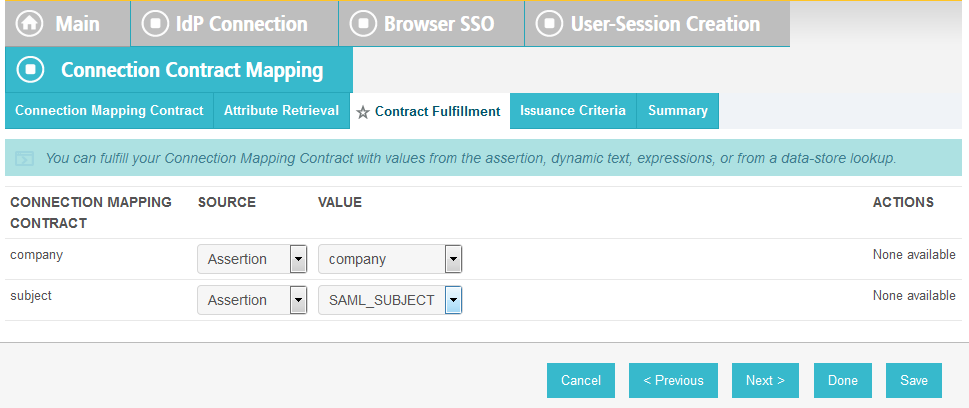
Click Save to complete the configuration.
6.4. Configure PingFederate-RP and SharePoint to Pass and Read Attributes
6.4.1. Configure PingFederate-RP to Pass Attributes to SharePoint
Once the PingFederate-IdP completes the authentication for a user, the IdP will send a SAML message to the PingFederate-RP. That SAML message will contain attributes. The PingFederate-RP will then take the attributes and send them to SharePoint via WS-Federation.
Follow the instructions below to configure the PingFederate-RP to pass attributes and their associated values from the IdP to SharePoint. In the example below, the attribute being configured to be passed to SharePoint is the company attribute.
Launch your browser and go to https://<DNS_NAME>:9999/pingfederate/app. Replace DNS_NAME with the fully qualified name of the RP’s PingFederate server (e.g., https://rp.abac.test:9999/pingfederate/app).
Log on to the PingFederate application using the credentials you configured during installation.
On the Main menu under SP CONNECTION, click Manage All SP.
Click on the link for the WS-Federation connection to the SharePoint instance created in Section 3 (e.g., SharePoint).
On the Activation & Summary screen, scroll down to the Assertion Creation group.
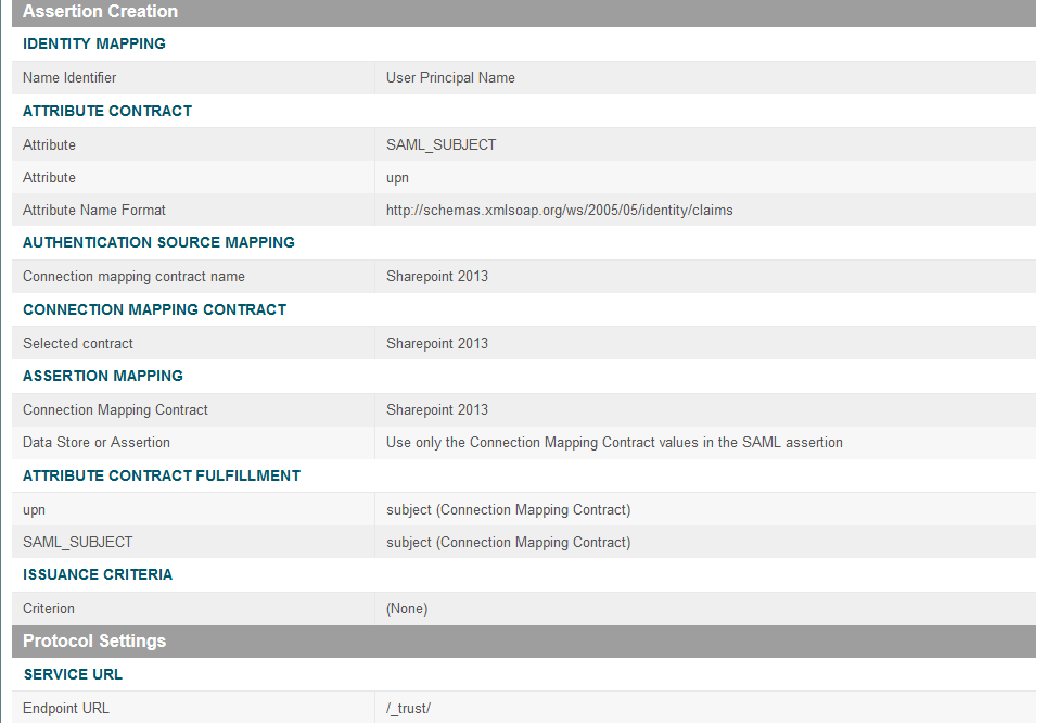
Click on the ATTRIBUTE CONTRACT link. On the Attribute Contract screen, under the EXTEND THE CONTRACT column, enter the name of the attribute (e.g., “company”) to be passed from the PingFederate-RP to SharePoint in the empty text field. For the ATTRIBUTE NAME FORMAT, select the schemas.xmlsoap.org 2005 identity claims format.
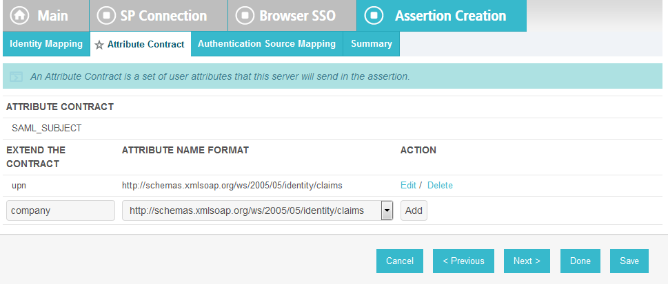
Click Add.
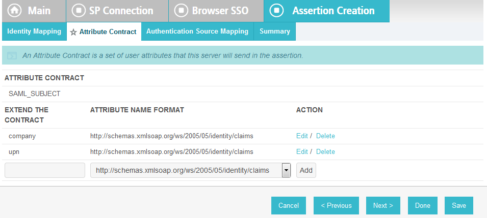
Click Done.
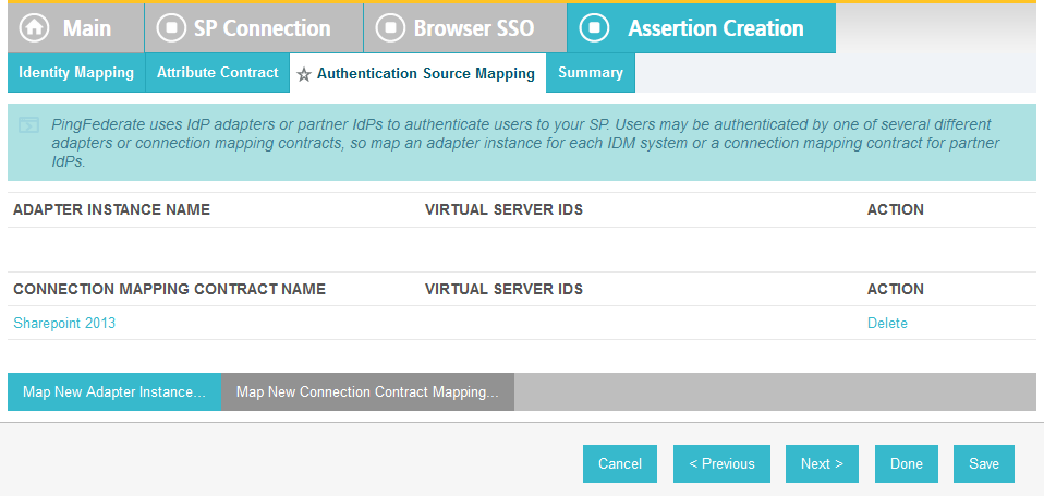
On the Authentication Source Mapping screen, under the CONNECTION MAPPING CONTRACT NAME heading, click on the name of the connection mapping contract (e.g., SharePoint 2013) between this PingFederate SP connection and the PingFederate IdP connection that was configured in the earlier section, Configure Relying Party to Pull Attributes from the Identity Provider’s SAML Exchange.
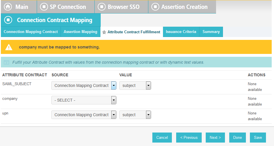
On the Attribute Contract Fulfillment screen, for the “company” attribute, select Connection Mapping Contract for the SOURCE field. Select company for the VALUE field.
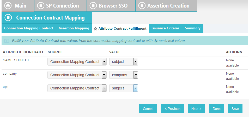
Click Save to complete the configuration.
6.4.1.1. Functional Test of PingFederate-RP Passing Attributes to SharePoint
The instructions in this section will help you perform a test to ensure that the PingFederate-RP is sending the correct attributes to SharePoint. The Firefox SAML tracer add-on is used to examine the SAML message.
Launch your Firefox browser and select SAML tracer from the Tools menu.
This will launch an empty SAML tracer window. Minimize the SAML tracer window. The SAML tracer will automatically record the details of the HTTPS messages in the background.
Go back to the main browser window and go to the RP’s SharePoint site (e.g., https://SharePoint.abac.test).
Select the option to use the federated logon (e.g., Federated Logon from Identity Provider). Your browser should be redirected to the PingFederate-IdP, and you should see the PingFederate Sign On screen.
Enter the Username and Password of the Microsoft AD account created earlier in this guide (e.g., lsmith). Note: If CISCO ISE has already been set up and 802.1x authentication has already occurred, this login is not necessary.
Click Sign On. On the RSA Adaptive Authentication screen, enter the SMS validation code received on your mobile phone. Click Continue.
Once authenticated at the IdP, your browser should automatically redirect to the PingFederate-RP (e.g., rp.abac.test) and then to the RP’s SharePoint (SharePoint.abac.test) site.
Go back to the SAML tracer window. Scroll down the list of messages and click on the POST message to SharePoint _trust URL to bring up the details of the message in the bottom pane.
Click on the Parameters tab for the bottom pane.
Copy all of the content (beginning with the POST line) in the bottom page and paste it into a text editor such as Notepad. Turn on Word Wrap to make it easier to see all of the XML content.
Scroll down the SAML message and locate the AttributeStatement node and sub-nodes.
For the AttributeStatement node and sub-nodes, enter some carriage returns before each XML tag to make it easier to examine the data. The goal is to be able to easily examine the Attribute nodes within the AttributeStatement node.

Expected Result: Within the AttributeStatement node, there should be multiple Attribute sub-nodes. There should be an Attribute sub-node that has an AttributeName value of “company.” The AttributeNamespace value should be http://schemas.xmlsoap.org/ws/2005/05/identity/claims. There should be an AttributeValue sub-node, which should contain the expected value (e.g., Conway Inc) for the “company” attribute that was pulled from Microsoft AD (e.g., <saml:AttributeValue> Conway+Inc </saml:AttributeValue>) for the specific user (e.g., lsmith) who authenticated at the Sign On screen.
6.4.2. Configure SharePoint to Read Custom Attributes from PingFederate-RP
The PingFederate-RP will send attributes to SharePoint via WS-Federation. Follow the instructions below to configure SharePoint to read the attributes and load them into the web session. In the example below, the attribute being configured to be read by SharePoint is the “company” attribute.
Using SharePoint administrator credentials, log on to the server that hosts SharePoint for the Relying Party.
Click on the Start menu and navigate to SharePoint 2013 Products group. Open SharePoint 2013 Management Shell.
Enter each of the commands displayed below the next paragraph into the Management Shell to configure a new attribute, “company,” for the existing Trusted Identity Token Issuer named “Federated Logon from Identity Provider,” Enter each command separately, and enter a carriage return after the command. If the command executed successfully, Management Shell will not provide any feedback. If an error occurs, Management Shell will display the error.
$tokenIssuer = Get-SPTrustedIdentityTokenIssuer -Identity "Federated Logon from Identity Provider"
$tokenIssuer.ClaimTypes.Add("http://schemas.xmlsoap.org/ws/2005/05/identity/claims/company")
$tokenIssuer.Update()
$claimmap = New-SPClaimTypeMapping -IncomingClaimType "http://schemas.xmlsoap.org/ws/2005/05/identity/claims/company" -IncomingClaimTypeDisplayName "company" -SameAsIncoming
Add-SPClaimTypeMapping -TrustedIdentityTokenIssuer $tokenIssuer -Identity $claimmap

6.4.2.1. Functional Test of SharePoint Reading Attributes from PingFederate-RP
The instructions in this section will help you perform a test to ensure that SharePoint can read the attributes sent in messages from the PingFederate-RP.
First, follow the instructions in this section to ensure that SharePoint is configured to read the newly configured attributes from PingFederate-RP.
Launch your browser and go the SharePoint central administration page (e.g., http://SharePoint.abac.test:44444/default.aspx).
Log on using the credentials of the SharePoint administrator.
Under the Application Management group, click on Manage Web Applications.
Click on the web application that contains the SharePoint site you are managing (e.g., SharePoint – 80). SharePoint highlights the web application row that you clicked.
Click User Policy.
Click the Add users link.
Click Next.
On the Add Users screen, click the small browse icon (looks like an open book) under the Users field.
Expected Result: On the Select People and Groups screen, you should see a grouping with the name of the trusted token issuer (e.g., Federated Logon from Identity Provider). You should also see the newly configured attribute (e.g., company) listed under that grouping.
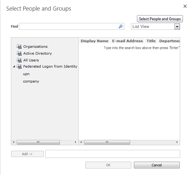
6.5. Configure the Claims Viewer Web Part at the SharePoint Site
Follow the instructions below to configure the Claims Viewer web part at the SharePoint site. The Claims Viewer is a component that is useful to the SharePoint administrator because it displays a list of the attributes that are loaded into the web session. This list can be used to validate that the correct set of attributes and associated values are being passed from the PingFederate-RP, and that SharePoint is correctly configured to read the attributes.
Log on to the server that hosts SharePoint for the RP.
Launch your browser and go the SharePoint central administration page (e.g., http://SharePoint.abac.test:44444/default.aspx). Log on using the credentials of the SharePoint administrator.
The central administration home page displays.
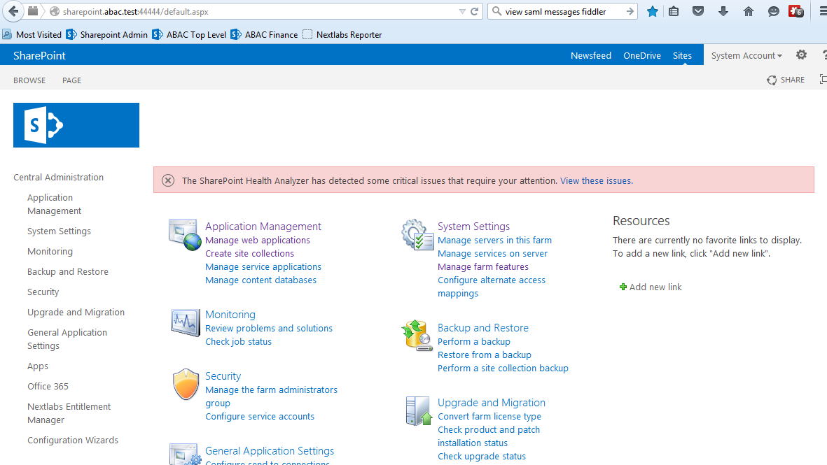
On the Central Administration menu on the left, click System Settings.
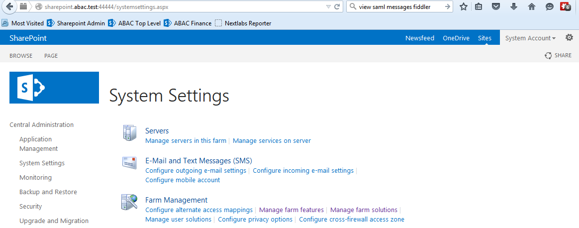
On the Farm Management menu, click Manage Farm Solutions.
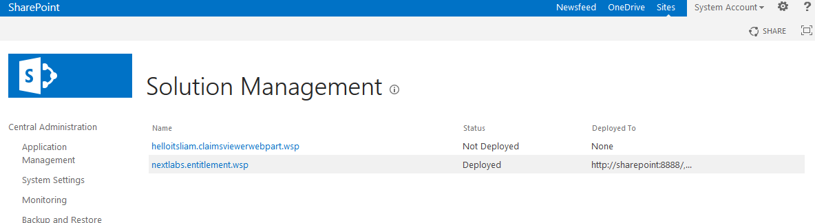
Click on the helloitsliam.claimsviewerwebpart.wsp link.
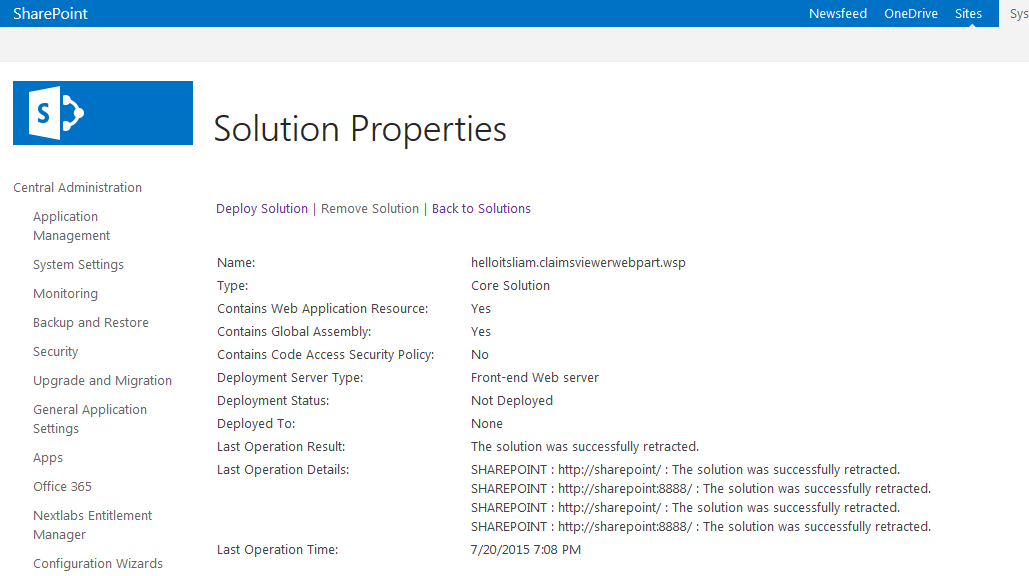
Click on the Deploy Solution link at the top of the page.
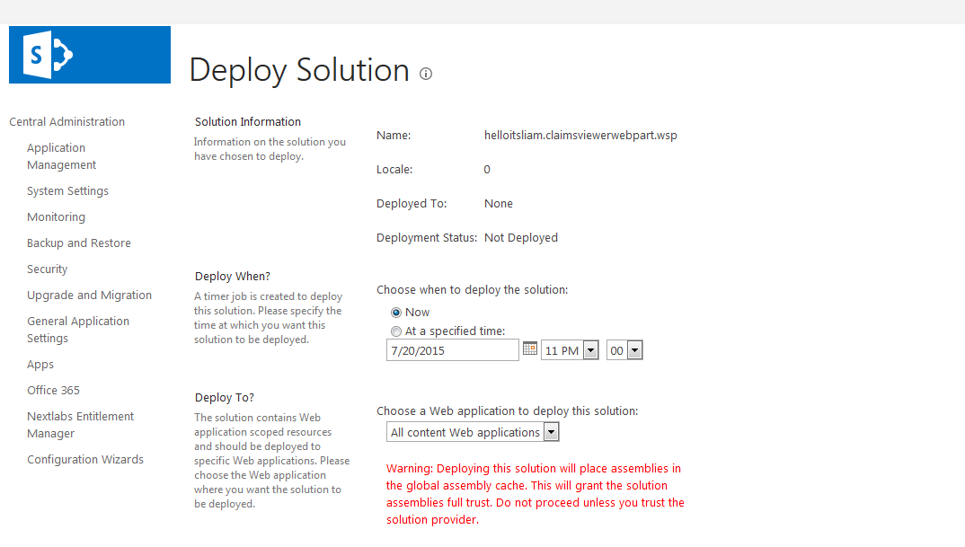
Click OK at the bottom of the page.
The claimsviewerwebpart should be shown as deployed on the Solution Management page.
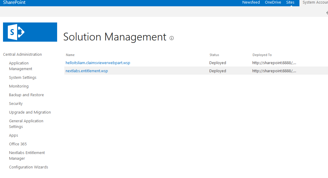
This completes the portion of the claims viewer web part configuration at the SharePoint central administration page.
6.5.1. Configure SharePoint Claims Viewer
This section explains how to add a new page to the SharePoint site to view the claims.
Log on to the RP’s SharePoint site (e.g., https://SharePoint.abac.test) using the credentials of the SharePoint administrator. Select Windows Authentication at the Sign On screen.
Click the gear icon at the top right corner of the page and select the Site Contents link.
Click on the Site Pages library. This will show a list of the existing pages on the site.
Click the new Wiki page link to add a new page. This link may be named differently, depending on your site’s SharePoint template. Enter a name for the new page (e.g., ClaimsView).
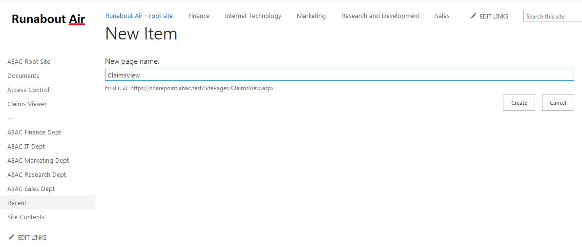
Click Create. The SharePoint page editor for the newly added page displays.
Click on the INSERT tab at the top of the page. Click on the Web Part button.
In the Categories list, select Custom. In the Parts list, select ClaimsViewerWebPart.
Click Add.
Click the SAVE button at the top right corner of the page.
SharePoint launches the new page (e.g., ClaimsView) that was just created. Save the URL of the new page (e.g., https://SharePoint.abac.test/SitePages/ClaimsView.aspx), because you will use it later in a functional test.)
The Claims Viewer Web Part on the page displays. It is collapsed by default.
Click on the + sign under ClaimsViewerWebPart to view the claims data. You will see a list of claim values and information about the SAML token at the bottom of the page.
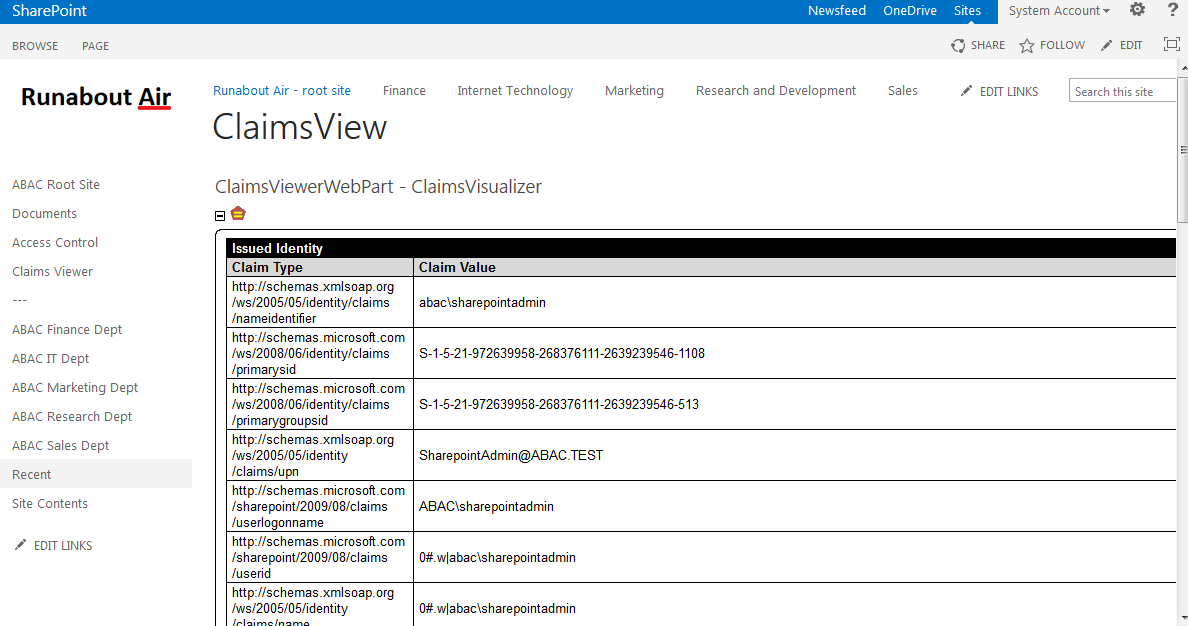
6.6. Functional Test of All Configurations for Section 6
The instructions in this section will perform an integrated test all of the configurations in Section 6. Using the browser, you will log on using an account that was created in Microsoft AD. Then you will use the SharePoint claims viewer to validate that the newly configured attributes are passed from the IdP to the RP and that the attributes are successfully loaded into the SharePoint web session.
Launch your browser and go to the RP’s SharePoint site (e.g., https://SharePoint.abac.test).
Select Federated Logon from Identity Provider.
Your browser is redirected to the PingFederate-IdP, and you see the PingFederate Sign On screen.
Enter the credentials of the Microsoft AD account created earlier in this guide (e.g., lsmith).
Click Sign On. On the RSA Adaptive Authentication screen, enter the SMS validation code received on your mobile phone. Then, click Continue.
Once authenticated at the IdP, your browser automatically redirects to the PingFederate-RP (e.g., rp.abac.test) and then to the RP’s SharePoint (SharePoint.abac.test) site.
Once you arrive at the SharePoint site home page, navigate to the claims viewer page that was created in the earlier section (e.g., https://SharePoint.abac.test/SitePages/ClaimsView.aspx). Expand the claims viewer web part on the page to see a list of claims.
Expected Result: You should see the newly configured attribute (e.g., company) and its associated claim value. The claims viewer shows the name of each attribute (i.e., claim) using a long format such as http://schemas.xmlsoap.org/ws/2005/05/identity/claims/company.
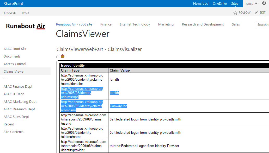
6.6.1. Temporarily Disable SAML Encryption for Testing and Troubleshooting Message Exchanges
Follow the instructions below to temporarily disable the encryption of SAML messages between the IdP and the RP. You should perform the steps in this section only when explicitly instructed to do so in another section of the guide (e.g., during a functional test). You may also need to refer back to this section in the future to test or troubleshoot SAML message exchanges in your environment.
Temporarily disabling the encryption can help test that the expected attributes are being exchanged between the IdP and the RP. By temporarily disabling the encryption, you will be able to see the attributes and their associated values in the SAML messages using the Firefox SAML tracer add-on or a comparable software tool. When testing or troubleshooting is completed, you can enable the encryption again.
6.6.1.1. Disable SAML Encryption
Launch your browser and go to https://<DNS_NAME>:9999/pingfederate/app. Replace DNS_NAME with the fully qualified name of the IdP’s PingFederate server (e.g., https://idp.abac.test:9999/pingfederate/app). Log on to the PingFederate application using the credentials you configured during installation.
On the Main menu under SP CONNECTION, click Manage All SP.
Click on the link for the SP connection for which you want to disable the encryption (e.g., https://rp.abac.test:9031).
Scroll down to the Protocol Settings group.
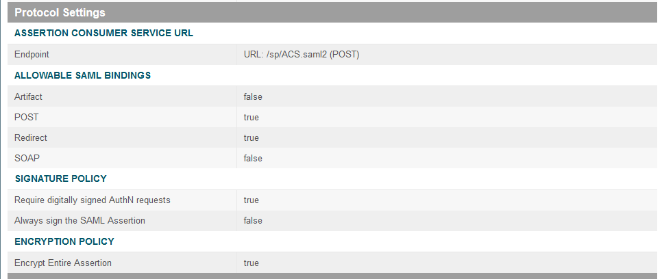
Click on the ENCRYPTION POLICY link.
On the Encryption Policy screen, select None.
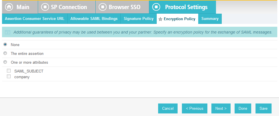
Click Save.
At this point, you have disabled SAML encryption at the IdP for this specific connection to the RP. You can perform authentication testing using the Firefox SAML tracer to examine the SAML messages being sent by the IdP to the RP.
6.6.1.2. Enable SAML Encryption again
Once testing is completed, follow the instructions below to enable the encryption once again.
On the PingFederate Main Menu under SP CONNECTION, click Manage All SP.
Click on the link for the SP connection for which you want to enable the encryption (e.g., https://rp.abac.test:9031).
Scroll down to the Protocol Settings group.
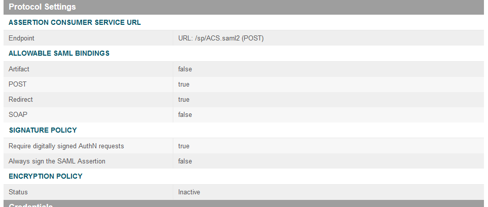
Click on the ENCRYPTION POLICY link.
On the Encryption Policy screen, select The entire assertion.
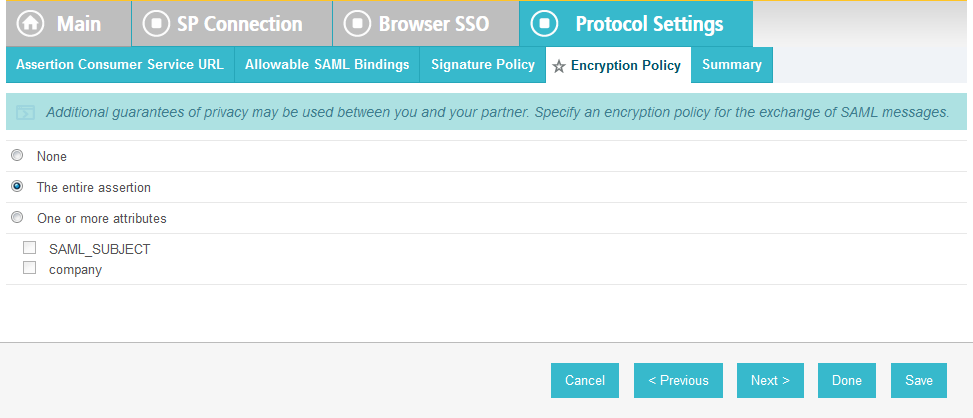
Click Save.
On the Select XML Encryption Certificate screen, select the Block Encryption Algorithm (e.g., AES-128), and the Key Transport Algorithm (e.g., RSA-OAEP). For the selection box above Manage Certificates, select the RP’s public key certificate to be used to encrypt the message content.
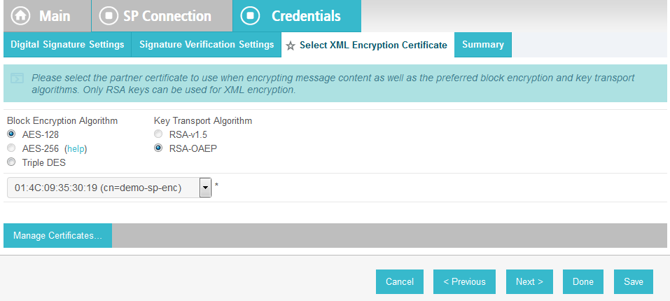
Click Save.
You have now enabled the encryption for the connection again.
7. Setting Up NextLabs to Protect SharePoint
7.1. Introduction
In this build we are using an ABAC architecture to protect resources on a Microsoft SharePoint instance. In this section, we will install the NextLabs Control Center, Policy Studio, Policy Controller, and Entitlement Manager for SharePoint Server. Before getting started installing these components, you must prepare your environment. At a minimum, Windows Server 2012 must be set up with a configured Active Directory, and SharePoint must be installed and configured with a Site Collection. If you haven’t already completed the basic installation and configuration of Windows Server 2012 and Active Directory, please refer back to Section 2, “Setting up the Identity Provider.” If you haven’t already completed the installation and configuration of SharePoint, please refer to Section 4, “Installing and Configuring Microsoft SharePoint Server and Related Components.”
The four NextLabs components installed in this How-To section provide an Information Control Platform (ICP), Policy Administration Point (PAP), Policy Decision Point (PDP), and Policy Enforcement Point (PEP) in the ABAC Architecture. Each component will be described generally in the Components section. Then there will be separate sections illustrating installation and configuration of each component. Finally, the Functional Test section will give some guidance for verifying the correct installation and configuration of the various components presented in this section.
7.2. Components
- NextLabs Control Center (release 7.5): enterprise-level Information Control Platform (ICP) for policy-driven data loss prevention and entitlement management; can contain many software components, including the following two in this build:
- Policy Studio: Enterprise Edition (PAP): application for policy lifecycle management, provides a graphical user interface (GUI) for defining and deploying ABAC policies. This product is installed on an instance of SQL Server.
- Policy Controller (PDP): distributed component of the Control Center that evaluates policies created in the PAP to determine a deny or allow decision when users attempt to access protected resources. This product is installed on an instance of Microsoft SharePoint Server.
- NextLabs Entitlement Manager for Microsoft SharePoint Server (PEP): enforces the decisions from the PDP to deny or allow access to SharePoint resources. this product is installed on an instance of Microsoft SharePoint Server.
7.2.1. NextLabs Control Center (release 7.5)
The NextLabs Control Center is an enterprise-level Information Control Platform (ICP). It integrates into existing IT infrastructure, and applications and can be used to digitally manage policies to govern data classification, access, sharing, and automate security compliance procedures. In order to fulfill its diverse capabilities, the Control Center can be configured to incorporate and coordinate many NextLabs software components. It is also possible to develop your own custom access control enforcers for applications that do not already have an available enforcer built by NextLabs. In this build, we take advantage of the Policy Studio, Policy Controller, and Entitlement Manager for Microsoft SharePoint Server, which are discussed in the following sub-sections.
In order to support administrative and configuration activities necessary for its many components, NextLabs Control Center provides a web application user interface called Administrator. Some of the system monitoring and administrative tasks available via Administrator include: checking how many policies are deployed in the network, finding out on which hosts the Control Center components are installed, checking the status of Control Center server components, finding out how many enforcers are currently running, finding out if any enforcers are disconnected, and finding out or modifying the current heartbeat setting for an enforcer, among others.
Another key component of the Control Center is the Policy Server. The Policy Server runs continuously from the moment of startup as a Windows service. As new policy is defined or policies are updated, the Policy Server pushes these policy sets to the Policy Controller on the SharePoint Server.
The Control Center platform is installed and configured on the same server as the build’s SQL database, which we refer to as the SQL Server.
7.2.2. NextLabs Policy Studio: Enterprise Edition
The NextLabs Policy Studio component of the Control Center is intended for administrators and policy designers responsible for converting the general data access and usage management goals of the enterprise into deployable, active policies. Depending on a company’s business rules, policies can be defined to evaluate user (subject) attributes, resource (object) attributes, and environmental (contextual) attributes.
The Policy Studio provides a graphical user interface with which you can create an abstract model representing the various parts of the enterprise environment (users, applications, computers, and environmental context), construct policies with these modeled components, and fine-tune policies using advanced conditions that can change based on dynamic comparisons, evaluations, and contextual factors. For example, policy designers can select pre-defined conditions including the time of day, day of the week, connection type, and IP address, among many others. In addition to defining which attributes to evaluate when making an enforcement decision, the policy construction process can also determine notification obligations such that when a policy is allowed or denied, a user can be notified with a default or custom message, a statement can be added to the application’s log file, and an email can be sent to an administrator.
Like the Control Center platform, the Policy Studio is installed and configured on the SQL Server.
7.2.3. NextLabs Policy Controller
Each NextLabs Policy Controller provides the interface to the Policy Server component of the Control Center (installed on the SQL Server), and serves as a distributed Policy Decision Point (PDP). It comprises a set of software modules delivered with Control Center, read-to-install on the enforcer host or development machine. Because it is not specific to any adapter type, it requires no customization. In this build, the Policy Controller is installed and configured on the same server as the SharePoint instance, which we refer to as the SharePoint Sever.
In general, the logical architecture of a NextLabs enforcer that protects an application (such as the Entitlement Manager for SharePoint Server, covered in the next sub-section) consists of two parts, the Policy Controller and the Policy Adapter.
The Policy Controller consists of the following functional components:
The Policy Evaluation Engine evaluates whether or not each user action is covered by any of the policies currently cached at that enforcement point. It bases its evaluation on multiple criteria such as who the user is, what host he is using, how he is connected to the network, which action is being attempted, on what resource, the date, the time, and so on. It does this in real time, and operates continuously whether the host is connected to the network or not. Note that while disconnected from the network the local encrypted bundle.bin policy cache would not be able to be updated from policy changes made in the PAP.
Note: Policies are authored in the PAP GUI on the SQL Server, and any modifications to the policy set are transmitted by the Policy Server, also installed on the SQL Server, to the Policy Controller on the SharePoint Server. It takes a heartbeat length of time for the updates to take effect on the SharePoint Server. By default, the heartbeat rate of the desktop enforcer is set to 60 minutes, which is appropriate for a live production environment. For testing and learning purposes, however, you should change this to 1 minute, which will allow you to define, deploy and test policies with shorter delays. A heartbeat can be configured via the Control Center Administrator web application.
The Context Manager keeps constant track of the environmental context of all events, and provides it to the Policy Engine and Policy Adapter. The context includes user identity, computer host name, network connection type, and date and time.
For any policy that evaluates as True, the Obligation Manager initiates an obligation by sending a request to a policy adapter’s obligation services or executing built-in obligations. It contains three sub-components:
Policy Logger - collects and logs all activity details and policy decision results
Messaging Services - sends message to recipients or targets listed in a policy
Application Extender - launches an application or custom executable that performs some custom obligation
The Controller Manager records non-policy activities, updates the configuration, and secures the controller. Components include:
Activity Recorder - records activities tracked by the policy adapter in real time.
Configuration Manager - applies profile and system configuration changes in real time
Policy Authentication - authenticates the policy set from the Policy Server and encrypts it on the local file system
Note: It is the responsibility of the Controller Manager to encrypt the bundle.bin file on the local file system for use during policy evaluation by the PDP.
Tamper Resistance Module - protects all Entitlement Manager processes, installed files, and registry settings from tampering by users or other processes, and governs the automatic start-up and restart features. The Policy Controller runs as a Windows service continuously from the moment of startup, called Control Center Enforcer Service.
The ICENet Client provides the interface for all communication with the Policy Server. It is used for deploying new or changed policies, periodically sending activity logs from each control point, and providing controller health status.
7.2.5. Required or Recommended Files, Hardware, and Software
| Component | Required Files | Recommended or Minimum Hardware Requirements | Hardware Used in this Build | Recommended or Minimum Operating System or Other Software | Operating System or Other Software Used in this Build |
|---|---|---|---|---|---|
| Control Center (CC) | license.dat; ControlCenter-64-7.5.0.0-64-201410211146.zip | 1GB RAM; 1GHz CPU; 4GB free disk space | Windows Server 2008, Enterprise Edition, R2, 64-bit, or Windows Server 2012; Java bundled and installed within NextLabs CC; Microsoft SQL Server 2012; Microsoft SQL Server Management Studio |
Windows Server 2012; Java bundled and installed within NextLabs software architecture; Microsoft SQL Server 2012; Microsoft SQL Server Management Studio | |
| External Database | N/A | 500 GB for table space | 500 GB for table space | Internal PostgreSQL; External, PostgreSQL, External Oracle, or External MS SQL Server | External MS SQL Server 2012 |
| Policy Studio | PolicyStudio-setup64-7.5.0.0-10-201410291227.zip | i3 or above, 1.5 GHz, dual-core CPU; 2GB; 10 GB free disk space |
Windows XP, Service Pack 3, 32-bit, Windows 7, 32-bit and 64-bit, or Windows Server 2008, Enterprise Edition, R2, 64-bit; Microsoft SQL Server 2012; Microsoft SQL Server Management Studio |
Windows Server 2012; Microsoft SQL Server 2012; Microsoft SQL Server Management Studio | |
| Policy Controller | PolicyController-CE-64-7.0.1.0-1-201405191624.zip | 2GB RAM; i3 or above, 1.5 GHz, dual-core CPU; 10 GB free disk space | Windows XP, Service Pack 3, 32-bit Windows 2003, 32-bit, Windows 7, 32-bit and 64-bit, Windows Server 2008, Enterprise Edition, R2, 64-bit, or Red Hat Linux Release 1, Updates 1-3 |
Windows Server 2012 | |
| Entitlement Manager for SharePoint Server | SharePointEnforcer-2013-64-7.1.3.0-7-201410101427.zip |
|
Microsoft SharePoint Server 2013 on Windows Server 2012 |
7.3. Installation and Configuration of NextLabs Control Center (on the SQL Server)
7.3.1. Installation and Configuration
7.3.1.1. Install the Microsoft SQL Server via Microsoft SQLServer 2012
Instructions available at the Microsoft SQLServer site: https://technet.microsoft.com/en-us/library/hh231622(v=sql.110).aspx.
Notes:
- Regarding installation of Microsoft SQLServer 2012: if you already completed the Section 4, “Installing and Configuring Microsoft SharePoint Server and Related Components,” this step will already have been completed.
- Regarding having a database dedicated to NextLabs: NextLabs recommends that for anything but a demo or testing environment, you should use a database running on its own dedicated server to store all system data, rather than rely on Control Center’s internal database. A dedicated database server is strongly recommended because policy enforcement data accumulates quickly and can reach a significant volume. The problem is not necessarily storage space, but the performance drag on other processes caused by database queries of large amounts of data.
7.3.1.2. Create a New Database and Database User for the NextLabs Control Center Installation and Administration
Open Microsoft SQL Server Management Studio and login to Microsoft SQL Server.
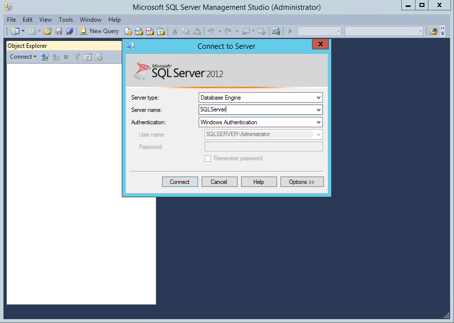
Right-click on Databases, left-click on New Database.
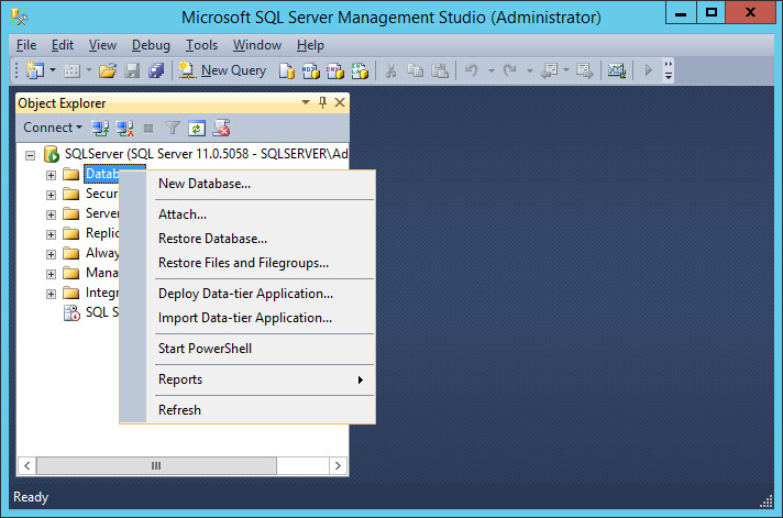
In the New Database window, specify a Database name that works for you. The application automatically copies this into the Logical Names of the Database files. Click OK. Example name from this build: nextlabs
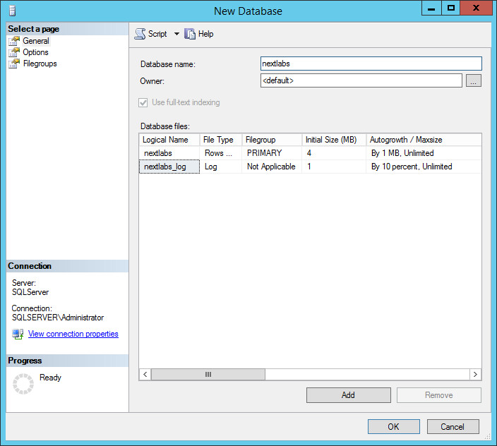
Click on the menu box next to Security to begin the process for creating a new login for the new NextLabs database’s administrator.
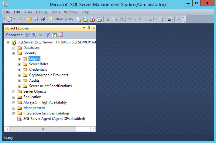
Right-click Logins. Left-click New Login.
Click on SQL Server authentication, and enter a new Login name and Password.

Click the menu box next to Logins. Right-click on the new user created in the previous step. Click Properties.

Click on User Mapping, then New Database. Under Database role membership for: [database_name], check the box next to db_owner.
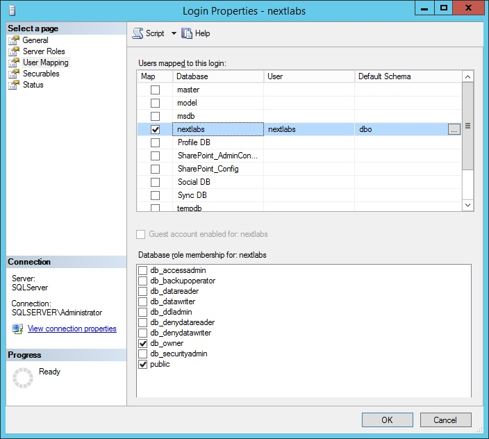
7.3.1.3. Install and Configure the NextLabs Control Center
Complete standard Control Center installation per NextLabs documentation available to customers, using the following steps:
Go to your Desktop or other known location where the required NextLabs Control Center installation files are stored. Example: C:\Users\Administrator\Desktop\NextLabs\Platform\7.5.0.0\
Note the location of the required license.dat file which will be needed later; example: C:\Users\Administrator\Desktop\NextLabs\Platform\License\license.dat
Right-click on ControlCenter-64-7.5.0.0-64-201410211146.zip and select Extract All from the floating menu. Wait for the files to be extracted.
Double-click to open the ControlCenter-64-7.5.0.0-64-201410211146 folder.
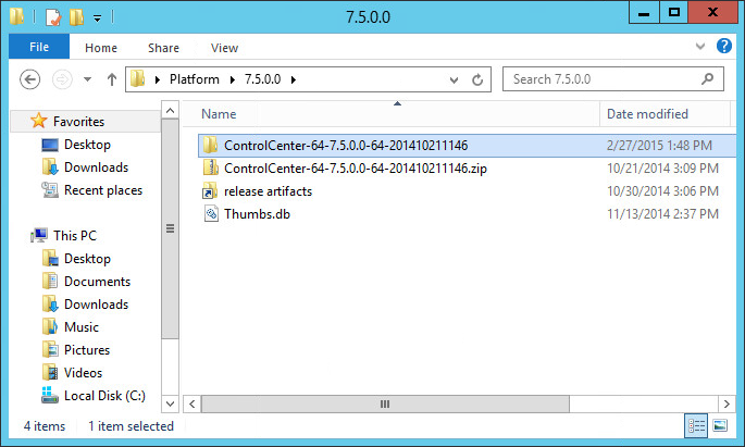
Right-click on ControlCenterServer-setup.exe, and select Run as administrator.
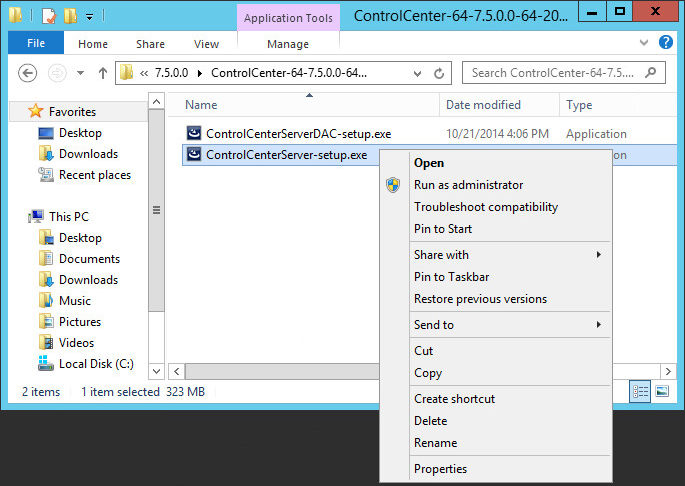
Click Next.

Select I accept the terms in the license agreement, then click Next.
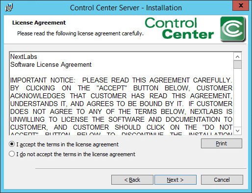
Click Next.

Select the Complete setup type. Then, click Next.

Enter the location of the license file in the License File Location field, or click Change to navigate to its location in Windows File Explorer. Click Next.
Example location: C:\Users\Administrators\Desktop\Platform\7.5.0.0\ ControlCenter-64-7.5.0.0-64-201410211146\license.dat
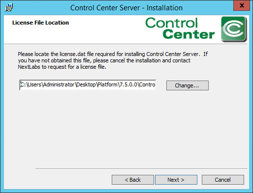
In the configuration wizard Super User password screen, enter a Password for the built-in administrative user for all Control Center Server applications. Click Next.
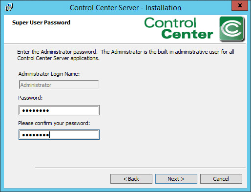
At the SSL Certificate Password screen, enter a Password to access the SSL certificates for the Control Center Server. Click Next.
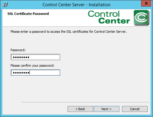
At the Encryption Key Store Password screen, enter a Password to access the Encryption Key Store for the Control Center Server. Click Next.

At the Application User Authentication screen, click Skip.
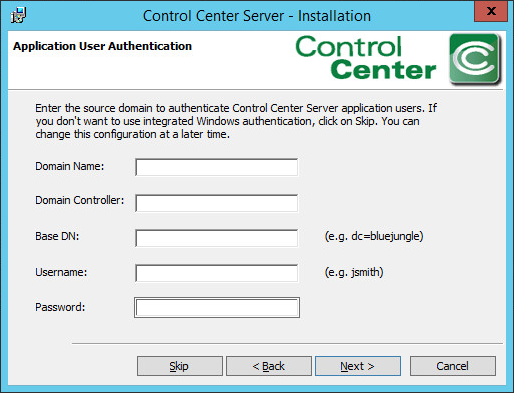
At the Control Center Server Database Location screen, select Store in an external Sql Server database instance. Click Next.
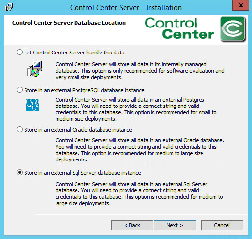
At the SQL Server Settings screen, do the following:
- Specify the Connect String, including the name of the new SQL database created. Example: nextlabs
- Specify Username (non-Super User) and Password.
- Click Next. Note: If the error Connection to the SQL database could not be established properly appears, it may help to restart the SQL Server.
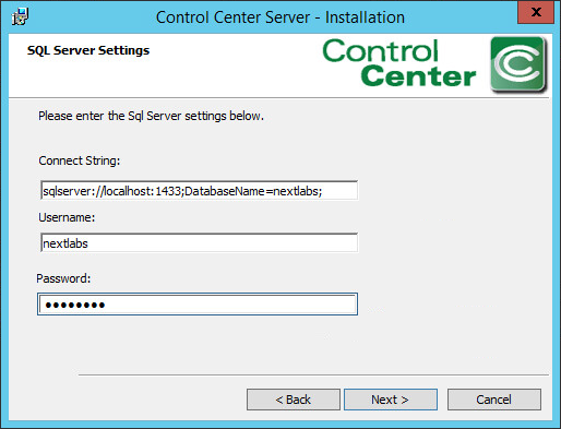
At the Port numbers window, the default port numbers are already entered: Web service port number: 8443, Web application port number: 443. Click Next.
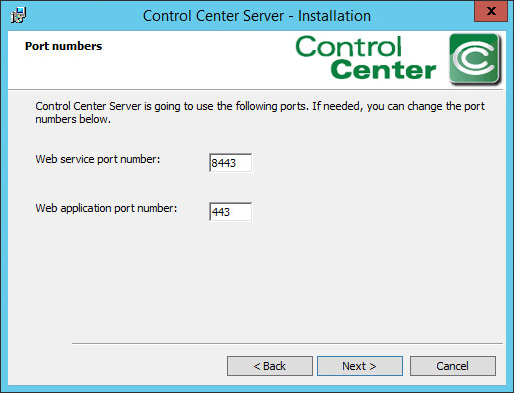
At the Mail Server Settings screen, click Skip.
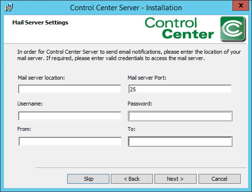
At the Ready to Install the Program screen, click Install.
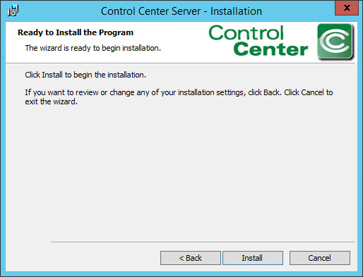
At the Installation Wizard Completed screen, click Finish.
Open an Internet browser and navigate to the following URL: https://localhost/administrator to login to the Control Center Administrator web application.
- If a security certificate warning comes up, click Continue to this website.
- Enter the Administrator (Super User) Username and Password.
- Click Login.

Once logged into the Control Center Administrator web application in your browser, you can verify that the NextLabs Control Center is installed and configured correctly on the SQL Server, and view the following information:
Fully qualified domain name (FQDN) of the server hosting the NextLabs Control Center. Example: SQLServer.ABAC.TEST
Services running on the host server, including but not limited to:
- Intelligence Server
- Dynamic Access Control
- Key Management Server
- Management Server
- Policy Management Server
For more information about these or other services running continuously via NextLabs Control Center on the SQL Server, please refer to NextLabs support documentation.
Port via which the above services are running. Example: 8443, default for web services
For each of the listed services, the default heartbeat period is 60 minutes, and can be modified via the Administrator (See step 23).
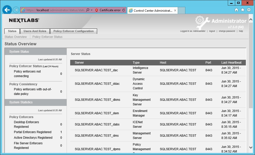
Click on the Policy Enforcer Configuration tab. The default Profile to open is the Desktop Enforcer Portal, with the Settings sub-tab defaulted also open. To change the heartbeat frequency for testing or debugging purposes, edit the Heartbeat Frequency field (minimum time is 1 minute). Click Save.
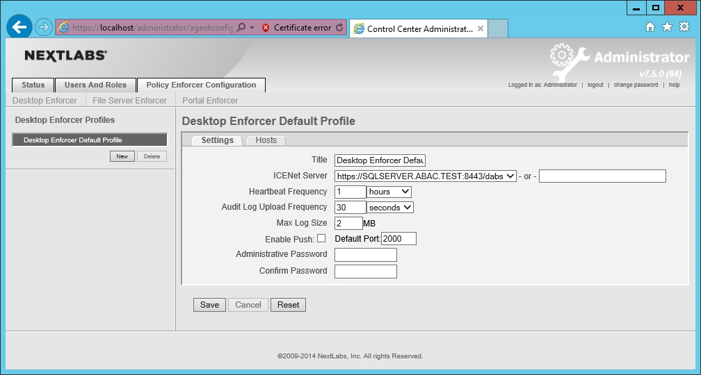
7.4. Installation and Configuration of NextLabs Policy Studio: Enterprise Edition (PAP)
7.4.1. Installation
Complete the standard Policy Studio installation per NextLabs documentation available to customers using the following steps:
On the SQLServer, go to your Desktop or other known location where the required NextLabs Policy Studio installation files are stored. Example: C:\Users\Administrator\Desktop\NextLabs\
Right-click on PolicyStudio-setup64-7.5.0.0-10-201410291227.zip and select Extract All. Wait for files to be extracted.
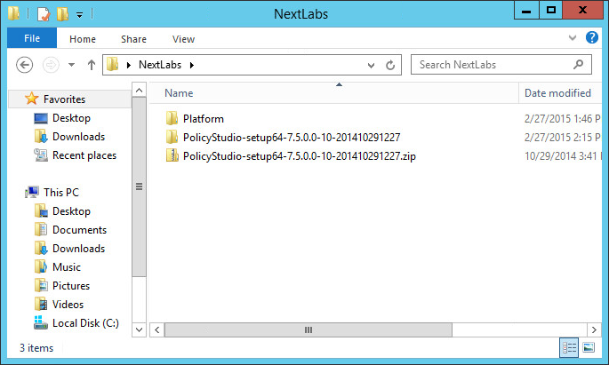
Double-click to open the PolicyStudio-setup64-7.5.0.0-10-201410291227 folder.
Right-click on PolicyStudio-setup.exe and select Run as Administrator.

At the Welcome to the Installation Wizard for Policy Studio screen of the Policy Studio Installation Window, click Next.
At the License Agreement screen, select I accept the terms in the license agreement, and click Next.
At the Destination Folder screen, click Next.
At the Policy Management Server Location screen, enter the default location localhost:8443. Click Next.
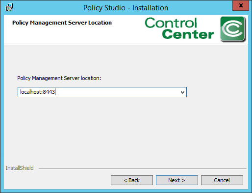
At the Policy Author Key Store Password screen, enter a Password and click Next.
At the Ready to Install the Program screen, click Install.

At the Installation Wizard Completed screen, click Finish.
In Windows Explorer, find and open the policystudio.exe application file.
- Double-click the C:/ drive.
- Double-click Program Files.
- Double-click NextLabs.
- Double-click Policy Studio.
- Double-click policystudio.exe.
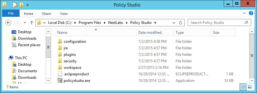
In the Control Center Policy Studio window, enter a User Name and Password to connect to the Policy Management Server
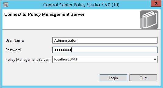
If the connection is successful, the Control Center Policy Studio - Policy Author window will open.
- Policies are defined and deployed in this interface, to be covered in Section 8.
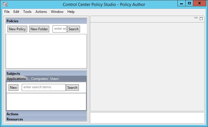
7.5. Installation and Configuration of Policy Controller (PDP)
7.5.1. Installation
To complete standard Policy Controller installation per NextLabs documentation available to customers, use the following steps:
On the SharePoint Server, go to your Desktop or other known location where the required NextLabs Policy Controller installation files are stored. Example: C:\Users\Administrator\Desktop\SharePoint\
Right-click on PolicyController-CE-64-7.0.1.0-1-201405191624.zip and select Extract All from the floating menu. Wait for files to be extracted.
Double-click on PolicyController-CE-64-7.0.1.0-1-201405191624 folder to open it.
Double-click CE-PolicyController-setup64.msi to begin installation.
At the Welcome to the InstallShield Wizard for NextLabs Policy Controller Installation screen, click Next.
At the License Agreement screen, select I accept the terms in the license agreement and click Next.
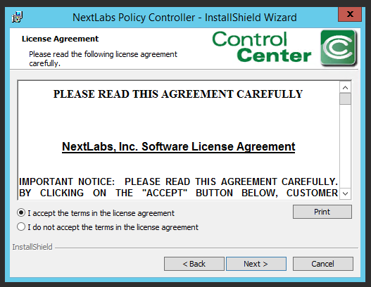
At the Destination Folder screen, click Next.
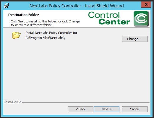
At the ICENet Server Location screen, enter the default ICENet Server Location: sqlserver:8443. Click Next.
At the Ready to Install the Program screen, click Install.
At the InstallShield Wizard Completed screen, click Finish.
In the window that immediately opens, click Yes to restart the computer, or click No to wait and restart after installing the PEP (see Section 7.6).
7.6. Installation and Configuration of NextLabs Entitlement Manager for SharePoint Server
7.6.1. Installation and Configuration
Note: Prior to installing the Entitlement Manager for SharePoint Server, it is necessary to install the NextLabs Policy Controller on the SharePoint Server. If you have not already installed the Policy Controller, please refer to Section 7.5 before proceeding.
7.6.1.1. Verify that a Web Application Site and Site Collection Already Exist in SharePoint
On the SharePoint Server, open an Internet browser and navigate to the following URL: http://sharepoint:44444 to login to the SharePoint Central Administration portal.
Enter the User Name and Password for your SharePoint Central Administration account, and click OK.

At the Central Administration page, click on Manage web applications under Application Management.
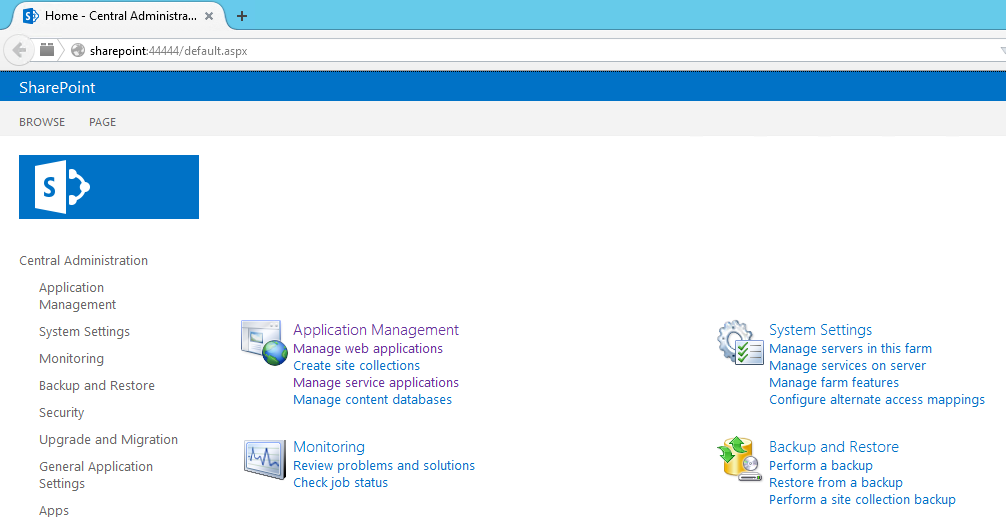
If they do not already exist, create a default Web Application site and add it to a basic Site Collection in SharePoint via Central Administration (See Section 4).

7.6.1.2. Install NextLabs Entitlement Manager for SharePoint Server
Complete the standard Entitlement Manager for SharePoint Server installation per NextLabs documentation available to customers using the following steps:
On the SharePoint Server, go to your Desktop or other known location where the required NextLabs Policy Controller installation files are stored. Example: C:\Users\Administrator\Desktop\SharePoint\
Right-click on SharePointEnforcer-2013-64-7.1.3.0-7-201410101427.zip and select Extract All from the floating menu. Wait for the files to be extracted.
Double-click on the SharePointEnforcer-2013-64-7.1.3.0-7-201410101427 folder.
Double-click on SharePointEnforcer-2013-64-7.1.3.0-7.msi to begin the installation.
At the Welcome to the InstallShield Wizard for NextLabs Entitlement Manager for MicroSoft SharePoint screen, click Next.

At the License Agreement screen, select I accept the terms in the license agreement and click Next.
At the Ready to Install the Program screen, click Install.
At the InstallShield Wizard Completed screen, click Finish.
After installing the IIS server must be reset:
- Click on the Windows icon and begin typing the word PowerShell
- When the Windows PowerShell application icon appears, double-click on the icon to open the Windows PowerShell
- From within the Windows PowerShell window, type in this command and press Enter to reset Internet Information Services: iisreset
7.6.1.3. Deploy Entitlement Manager for SharePoint Server to your SharePoint Farm
On the SharePoint Server, complete standard Entitlement Manager for SharePoint Server deployment per NextLabs documentation available to customers using the following steps:
On the SharePoint Server, click the Start icon to see the applications pinned to the Start menu.
Click on the NextLabs Entitlement Manager for SharePoint Server Deployment icon.
This shortcut is automatically pinned during the initial installation. In case the shortcut is not created automatically, the application can be opened from File Explorer at the location: C:\Program Files\NextLabs\SharePoint Enforcer\bin\NextLabs.Entitlement.Wizard.exe
At the Welcome to NextLabs Entitlement Manager for Microsoft SharePoint Deployment wizard screen, click Next.
At the System Check screen, after the system check is complete, click Next.
At the Farm Deployment Targets screen, select the applicable web application on which to deploy.
Note: if there is only one entry listed, i.e., http://sharepoint:44444/Central Administration, no web applications have been created. In that case, refer back to Section 7.6.1.1.
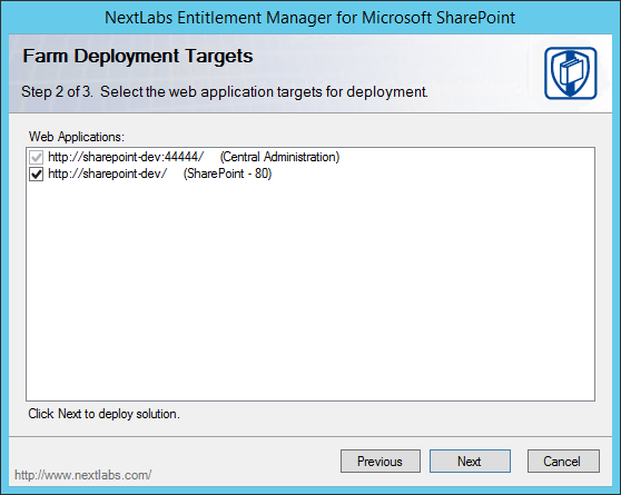
At the Deploying Step 3 of 3 screen, click Next.
At the Successful Deployment Completed screen, click Close.
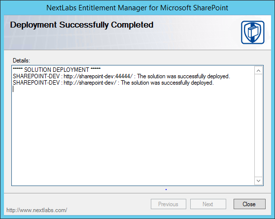
7.6.1.4. Enable Policy Enforcement on your Web Application via SharePoint Central Administration
On the SharePoint Server, open an Internet browser and navigate to the following URL: http://sharepoint:44444 to login to the SharePoint Central Administration portal.
Enter the User Name and Password for your SharePoint Central Administration account, and click OK.
Click on the NextLabs Entitlement Manager icon.
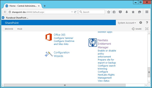
In the page that opens, scroll down to verify that the correct Web Application is chosen and the service is Enabled.
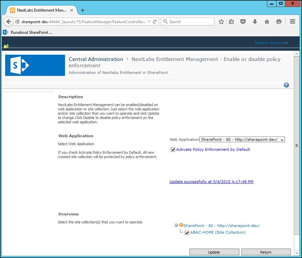
7.7. Functional Tests
7.7.1. Verify that the NextLabs Webpart for Policy Enforcement Has Been Successfully Enabled on the Site Collection in SharePoint
Similar to Section 7.6.1.4, complete the following steps to login to SharePoint Central Administration:
- Click on the Start icon.
- Click the NextLabs Entitlement Manager for SharePoint icon.
- Open SharePoint Central Administration and login as Administrator.
Click on Enable or disable policy enforcement under the NextLabs Entitlement Manager webpart.

Scroll down to the Web Application area to verify that the Entitlement Manager is activated for the correct SharePoint web application.

7.7.2. Test to Verify the NextLabs Service is Running
Click on the Windows Start icon.
Start typing the word Services.
Click on the Windows Services icon to open the list of running services.
Look for the NextLabs Policy Controller service called Control Center Enforcer Service.
Verify that the status is Running.
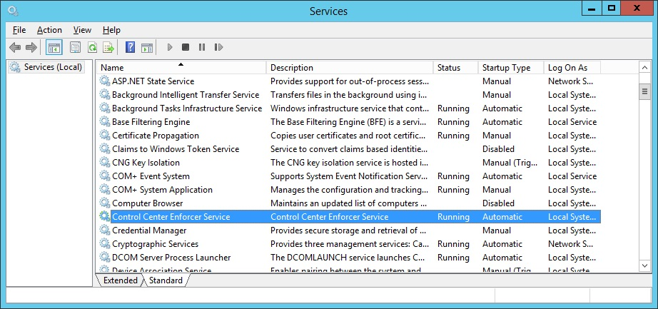
8. Defining Policies and Enforcing Access Decisions with NextLabs
8.1. Introduction
In previous sections of this How-To Guide, we installed several NextLabs products that can be used to define and deploy Attribute Based Access Control (ABAC) policies, and enforce decisions regarding user access to Microsoft SharePoint resources based on user, object, and environmental attributes, and the corresponding policies in place. This How-To Guide will illustrate how to use and configure NextLabs Policy Studio, the product responsible for Policy Lifecycle Management, and discuss policy strategy and the translation of business logic into policy.
Within Policy Studio, we will define and deploy policies and policy components. In NextLabs, the word Component is a named definition that represents a category or class of entities, such as users, data resources, or applications; or of actions, such as Open or Copy. Components are similar to using parts of speech to construct policy statements. For example:
- Noun: All employees in the human resources department or Any file with an .xls extension
- Verb: Copy, Print, or Rename File
Deployment is simply the distribution of new or modified policies and policy components to the appropriate enforcement points on desktop PCs, laptops, and file servers throughout the organization. This means you can create, review and refine policies as long as you like, but they are not enforced until you actually deploy them.
Finally, the Functional Test section will illustrate how to ensure that policies are being updated, evaluated, and enforced on Microsoft SharePoint.
8.1.1. Components and Sub-Components Used in this How-To Guide
NextLabs Policy Studio –provides the Policy Administration Point of the ABAC architecture. This component was installed with the rest of the NextLabs product suite used in this implementation in Section 7. Policy Studio provides the graphical user interface for Policy Lifecycle Management (defining, deploying, modifying, and deactivating policies).
- Located on the SQL Server
NextLabs Policy Server SharePoint Enforcer configuration file
- Automatically exists after NextLabs Control Center installation
- Located within the NextLabs software architecture on the SQL Server
NextLabs AgentLog and bundle.bin files
- Automatically exist after NextLabs Policy Controller installation
- Located within the NextLabs software architecture on the SharePoint Server
8.1.2. Pre-requisites to Complete Prior to this How-To Guide
If you intend to do a setup without identity federation and federated logins, you must:
If you intend to incorporate a trust relationship between an IdP and RP, and use federated logins into SharePoint, you must:
- Install and configure Active Directory (see Section 2).
- Setup and configure the RP and IdP (see Section 3).
- Install and configure Microsoft SharePoint (see Section 4).
- Configure the SharePoint federated login with the RP (see Section 5).
- Configure the attribute flow between all endpoints (see Section 6).
- Install and configure NextLabs Control Center, Policy Studio, and Policy Controller (see Section 7).
8.2. Policy Strategy
8.2.1. Top-Level Blacklisting Deny Policy, Whitelisting Allow Sub-Policies
In order to demonstrate a policy set with high security and fine-grained control, we employed a general blacklisting, then fine grained whitelisting sub-policy strategy for the policies. We chose this strategy because we considered it a more secure paradigm for securing SharePoint resources. Using this strategy, the access control logic initially applies a general deny all access decision at the top level for a given set of related attributes, then specifies conditions under which access can be allowed in various sub-policies based on sufficient correlating user, resource, and/or environment attributes. For example, later in this guide we will describe a policy set in which we initially deny all users on resources that have a sensitivity level attribute, however there is a sub-policy that specifies that a for resources at sensitivity level 2, allow users with a clearance attribute of Secret during regular business hours. The alternative to this approach would be to apply a general allow all access decision at the top level initially, then specify conditions under which users should be denied access. Because there can be many unforeseen edge cases that may not be anticipated by a business protecting its assets, we consider the general blacklisting, then whitelisting sub-policies approach a more feasibly secure solution. According to our strategy, any time a user, resource, or environment attribute does not comply with a whitelisting sub-policy to allow access, the access decision will default to deny.
8.2.2. Global Policies
In addition to the blacklisting versus whitelisting approach taken in our policy strategy, we also employed the use of global policies. The term global policy refers to the general applicability of the policy sets to more than one user and more than one resource at a given time. We defined our policies such that they have global effects and do not apply only to very specific use cases by themselves. The collective logic taken from the multiple global policies in place applies to the many kinds of access events that must be controlled according to a business’s complex and distributed business rules, which we describe below in Section 8.3.
8.3. Translation of Business Logic into Policy
8.3.1. ABAC Build Scenario – Runabout Air Business Rules
In previous sections of our Practice Guide we have constructed an example business scenario where an airline company, Runabout Air, has acquired another airline company, Conway Airlines. In this scenario the two companies have not yet merged their active directory forest and established a trust relationship such that historically Conway Airlines employees will be able to access resources on the Runabout Air SharePoint according to policies that correspond to Runabout Air’s business rules. The business rules we based our policies on are, generally:
- Some documents are more sensitive than others, and should be marked in SharePoint at different sensitivity levels. These documents should be strictly protected, and access should be restricted to Runabout Air’s normal business hours. Also, users should only be granted access to sensitive documents if they have sufficient clearance.
- Users should only be able to access documents that belong to their department, or to the departments relevant to them in the case of some instances of a need for cross-department access, i.e., business intelligence employees should have access to both sales and marketing department documents.
- Some documents are time-sensitive and pertain to system or other business maintenance, and should be marked in SharePoint as maintenance documents. These documents should only be accessed outside of Runabout Air’s normal business hours, so as to reduce the likelihood of disruption of normal business operation.
- There are times when a suspicious IP address or range of addresses should be blocked from accessing any SharePoint resources, or when a user from a particular IP address or range of IP addresses should only have access to low-sensitivity documents. There must be a mechanism in place to ensure access is denied for users attempting to access any high-sensitivity documents from an environment with that IP address or within a given IP address range.
8.3.2. Translation of Runabout Air Business Rules into ABAC Policies
ABAC Policies created from the above business rules might look like this:
Top-level sensitivity policy: default to deny access to all users attempting to access resources that have a sensitivity level attribute defined in SharePoint as greater than 0, unless explicitly allowed access by a sub-policy.
- For documents whose sensitivity attribute is defined as 1, allow access any time of day, any day of the week, to users with a clearance attribute of None, Secret, or Top Secret.
- For documents whose sensitivity attribute is defined as 2, allow access between the hours of 6am and 6pm for users with a clearance attribute of Secret or Top Secret.
- For documents whose sensitivity attribute is defined as 3, allow access between the hours of 6am and 6pm for users with a clearance attribute of Top Secret.
Top-level department policy: default to deny access to all users attempting to access resources that have a department attribute and project status defined in SharePoint.
For users whose department attribute is defined as a value equal to the document’s department attribute value, allow access for documents with a project status of any value.
For users whose department attribute is Business Intelligence, allow access for documents with a department attribute of Sales or Marketing and with a Project status of any value.
Note: The Project status metric is necessary because the department attribute is defined at the site level within SharePoint. Restricting users based only on the resource’s department attribute in this policy set results in the user being stuck in a deny access loop, no longer being able to access the Runabout Air root site and navigate to their correct department’s documents. Because each document has a project status attribute defined in addition to the department attribute, the policies can specify the targets of this policy as having both project status and department attributes defined, even though the department attribute is the most pertinent attribute for enforcing the access control relating to department access rules.
Top-level maintenance policy: default to deny access to all users attempting to access resources that have a maintenance attribute defined in SharePoint
- For documents whose maintenance attribute is defined as no, allow access to users, any time of day, any day of the week.
- For documents whose maintenance attribute is defined as yes, allow access to users between 6pm and 6am, any day of the week.
Top-level IP Address policy: default to deny access to all users attempting to access resources that have a sensitivity attribute defined in SharePoint.
- For documents whose sensitivity attribute is defined as 1, allow access to any user from an environment with any IP address defined.
- For documents whose sensitivity attribute is defined as 2 or 3, allow access to users coming from an environment with an IP address other than a restricted IP or one within a restricted IP range.
8.4. Using the NextLabs Policy Studio GUI for Policy Definition and Deployment
In this section, we will provide step-by-step instructions for how to define, deploy, modify and re-deploy, and deactivate necessary policy components and policies within Policy Studio. The examples we will use correspond to the Runabout Air business rules and ABAC policies described in Section 8.3.1 and Section 8.3.2. Note that Policy Studio was installed on the SQL Server, which is where all of the activity in Section 8.4 occurs.
8.4.1. Login and Initial Screen in Policy Studio
Given you have followed the instructions found in Section 7, follow these instructions to login to the NextLabs Policy Studio:
In Windows Explorer, find and open the policystudio.exe application file:
- Double-click the C:/ drive.
- Double-click Program Files.
- Double-click NextLabs.
- Double-click Policy Studio.
- Double-click policystudio.exe.
In the Control Center Policy Studio window, enter User Name and Password, then click Login to connect to the Policy Management Server.
If login was successful, you will see the Policy Studio’s graphical user interface, specifically the main screen where new policies and new components are defined, deployed, modified, and deactivated. Note the Policies panel in the top-left, the Components panel in the bottom-left, and an open space to the right where editing panels emerge for editing the policies and components.
After following the instructions in this section to define and deploy several user and resource components, as well as four policy sets, the Policy Studio interface will show the new components and policies populated in the left-side panel.
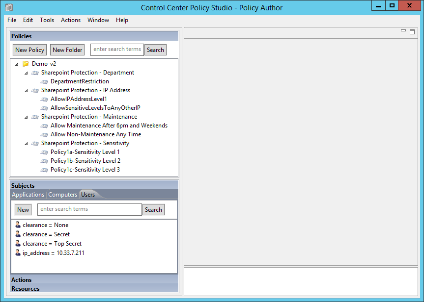
8.4.2. Policy Studio Menu Commands
Below are some of the Policy Studio menu commands used in this How-To Guide, along with explanations for what action they perform.
Extracted from the NextLabs Policy Studio User guide available to customers:
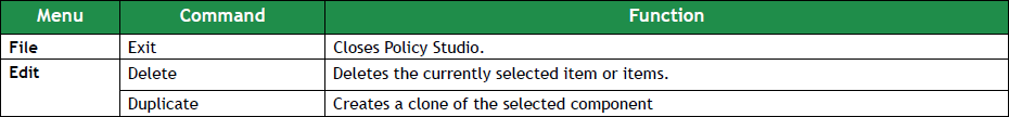
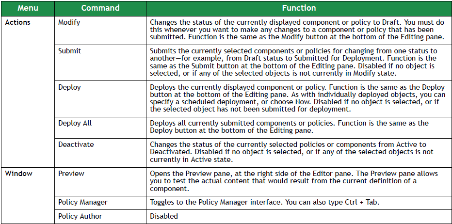
8.4.3. Defining and Deploying Components
8.4.3.1. Explanation of Components in NextLabs
According to the NextLabs Policy Studio User Guide available to customers, it is necessary to define components to represent various kinds of entities in your information environment. There are several times when you might want to define a new component:
- After setting up your Control Center system, before constructing policies for the first time (which is the reason here at this point in our How-To literature)
- When new classes of information or users come under the control of information policy
- When a new policy requires a policy component that has not yet been created
- When conditions at the organization change in any way that adds new items to be covered by information control policies. For example, if the company reorganizes and adds a new division, you might need a new policy component to represent the employees in that division.
Furthermore, when you are constructing a component, you do not need to save your work explicitly. Work is automatically saved as you go. If you are interrupted while working on a policy component, or want to work on another task and return to constructing the policy component later, you can stop and continue the constructing process as desired. Your work will be saved in draft status. You can find the policy component later in the appropriate component panel.
8.4.3.2. Defining and Deploying User Components
According to the Runabout Air business rules in Section 8.3.1 and ABAC policies in Section 8.3.2, it is possible that you may need to create a User Component to match the following conditions: user clearance attribute, user department attribute, and user IP address. This is correct except for the user department attribute. Because of the cross-departmental access of Runabout Air’s Business Intelligence employees, we use logical syntax instead of graphical components while defining that policy. Also, a note regarding the user IP address component: even though IP address is an environmental attribute, it can be configured in NextLabs as a user attribute coming from SharePoint Claims, or as a resource attribute, which requires different configuration in NextLabs. For our example we use the IP Address from SharePoint Claims, which is handled as a user attribute.
8.4.3.2.1. Clearance Components
Clearance = None
In the Components panel in the bottom-left of the Policy Studio window, click on the Subjects heading, and then click on the Users tab. Then click New to create a new component.
In the Create New User Component window, enter a descriptive component name, such as clearance = None. Click OK.
In the component editing panel you will see the following:
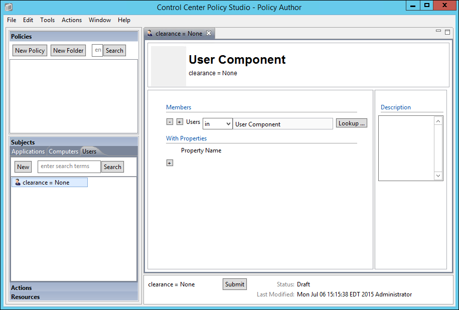
In the editing panel, click on the plus sign box under Property Name and enter clearance in the property name text box, keep the default is as the action, then enter None into the value text box. Click Submit.
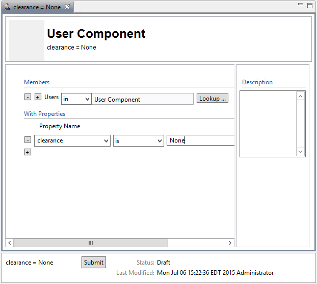
In the Submit window, click Submit.
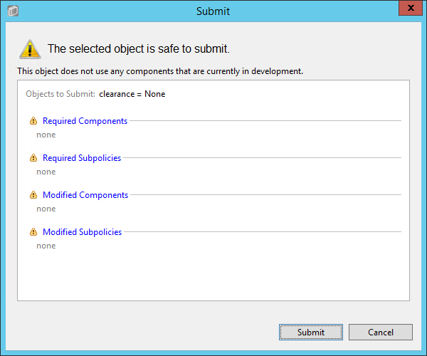
From the component editing panel, note the differences. The new status reads Submitted for Deployment. Click Deploy.
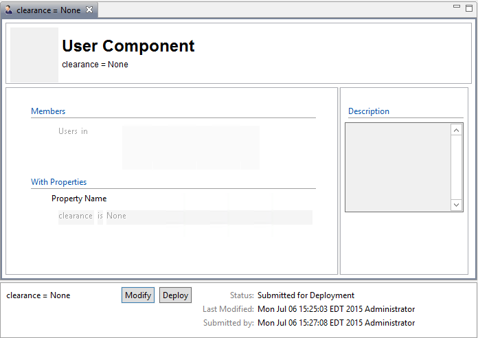
In the Deploy window, click OK. Note: You may deploy immediately, which we choose in our example. You could also deploy the following day at midnight, or at a different specific date and time.
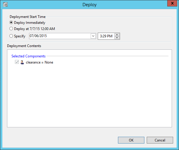
Verify at the bottom of the component editing panel that the Status now reads Pending Deployment. This will remain for the duration of the heartbeat (described in Section 7).
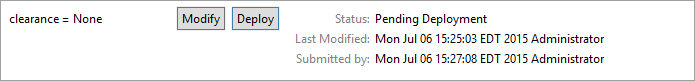
After the duration of the heartbeat has passed, Status will then read as Deployed. This indicates that the component is actively deployed in your ABAC system.
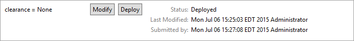
Clearance = Secret
The easiest way to create additional attribute components is to duplicate existing ones. To duplicate the existing user attribute component:
From the Component panel, highlight the name of the existing component, i.e., clearance = None
Click on Edit from the menu toolbar at the top of the window and select Duplicate from the drop-down menu, or right-click on the component and select Duplicate from the floating menu:
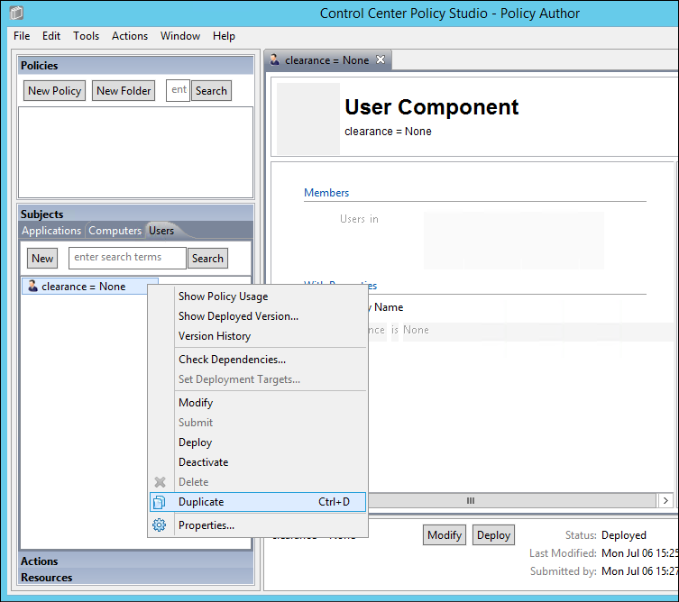
In the Duplicate window, edit the name of the new component, i.e., clearance = Secret. Click Save.
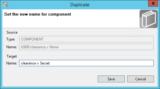
Edit the property value to match the component’s purpose, i.e., Secret. Click Submit.
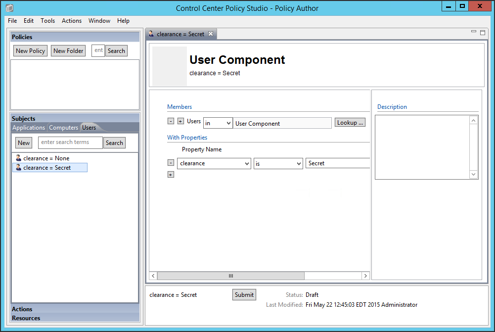
Repeat steps 5-9 from Section 8.4.3.2.1.1 to Submit and Deploy this component.
Clearance = Top Secret
- Repeat steps 1-5 in Section 8.4.3.2.1.2 for duplicating a new user attribute component. The new component should be named clearance = Top Secret, and the property value should equal Top Secret.
8.4.3.2.2. IP Address component
Repeat steps 1-3 in Section 8.4.3.2.1.2 for duplicating a new user attribute component. The new component should be named ip_address = 10.33.7.211.
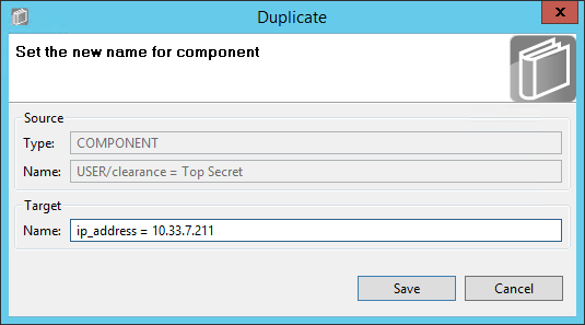
From the component editing panel, edit the Property Name to ip_address and the value to 10.33.7.211, leaving the default action is. Then click Submit.
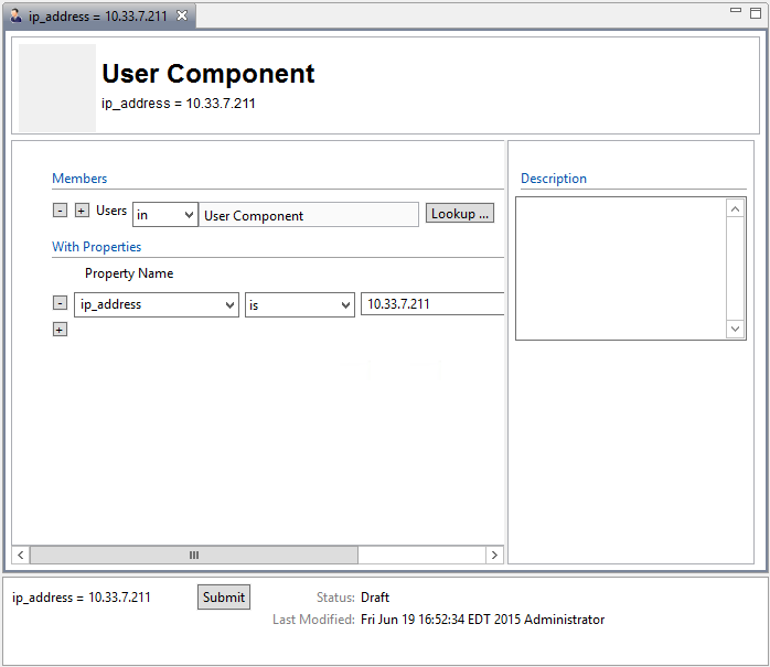
Repeat steps 5-9 from Section 8.4.3.2.1.1 to Submit and Deploy this component.
8.4.3.3. Defining and Deploying Resource Components
8.4.3.3.1. Maintenance components
Maintenance = yes
In the Components panel in the bottom-left of the Policy Studio window, click on the Resources heading, and then click on the Portals tab. Then, click New to create a new component.
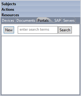
Enter a descriptive component name, such as maintenance = yes, then click OK.

In the editing panel, click on the plus sign box under Property Name and enter maintenance in the Property Name text box, keep the default is as the action, and enter yes into the value text box. Then click Submit.
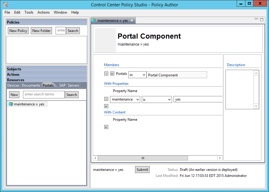
Repeat steps 5-9 from Section 8.4.3.2.1.1 to Submit and Deploy this component.
Maintenance = no
Similar to the steps taken for duplicating user components, do the following to duplicate the existing resource maintenance component to create the other resource components.
In the Component panel in the bottom-left corner of the Policy Studio interface, right-click on the maintenance = yes component. In the floating menu, select Duplicate.
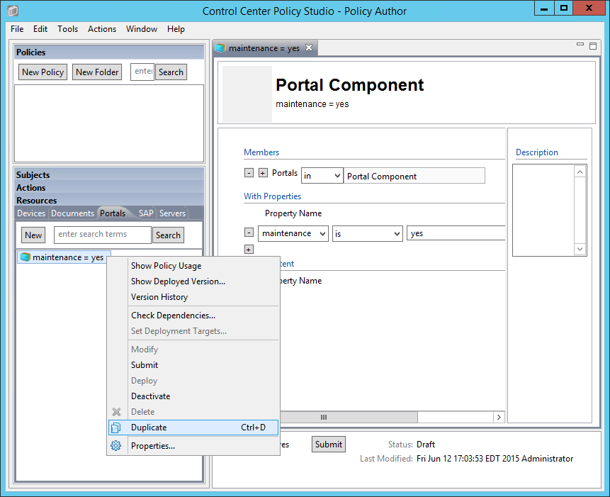
In the Duplicate window, edit the name of the new component. Example: maintenance = no.
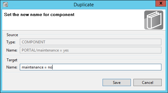
In the component editing panel, change the property value to no and click Submit.
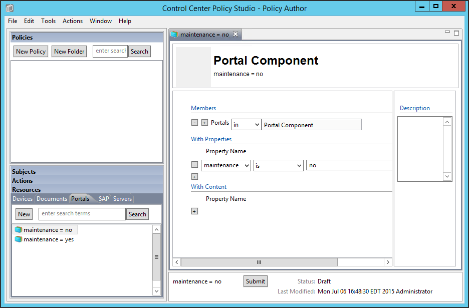
Repeat steps 5-9 from Section 8.4.3.2.1.1 to Submit and Deploy this component.
8.4.3.3.2. Sensitivity components
Sensitivity = 1
Repeat steps 1-4 from Section 8.4.3.3.1.2 to duplicate an existing resource component to create the Sensitivity = 1 component.
Sensitivity = 2
Repeat steps 1-4 from Section 8.4.3.3.1.2 to duplicate an existing resource component to create the Sensitivity = 2 component.
Sensitivity = 3
Repeat steps 1-4 from Section 8.4.3.3.1.2 to duplicate an existing resource component to create the Sensitivity = 3 component.
8.4.3.3.3. Project status component
Project status = any
Repeat steps 1-4 from Section 8.4.3.3.1.2 to duplicate an existing resource component to create the Project status = any component.
Note: Before the Submit step, in the component editing panel, enter the property value as *.

8.4.4. Defining Policy
After following the steps to define and deploy components in Section 8.4.3, you can continue on to define policies that relate to the Runabout Air scenario business rules discussed in Section 8.3. In order to define policies in Policy Studio, login as described in Section 8.4.1.
8.4.4.1. Creating a Policy Set Folder
Before being able to create any policies in Policy Studio, first you must create a folder, or choose an existing one.
From the main Policy Studio window, click New Folder.
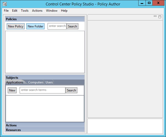
Enter the name of your folder and click OK.

8.4.4.2. Defining Department-based Policy Set
8.4.4.2.1. Defining the Top-level Department Policy that Enforces a General Deny Decision
In the Policies panel in the top-left corner of the main Policy Studio window, click on your new folder to highlight it. Then click New Policy.
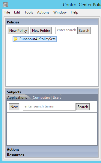
In the Create New Policy window, enter a name for the new policy. From the Policy Type drop-down menu, select Document Policy (which applies to all SharePoint policies). Click OK.
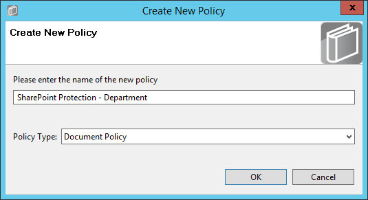
The new policy opens automatically in an editing panel. For this policy, keep the default Deny enforcement. Make these edits:
- In the On Resources area, click on the plus sign box next to Target. This automatically populates in and Resource Component.
- In the Condition Expression enter the ACPL: (resource.portal.department = “*” AND resource.portal.project status = “*”)
- In the Obligations area, check the Display User Alert box in order to customize the deny message displayed to the user when access is denied.
In the policy editing panel, your policy should look like this:
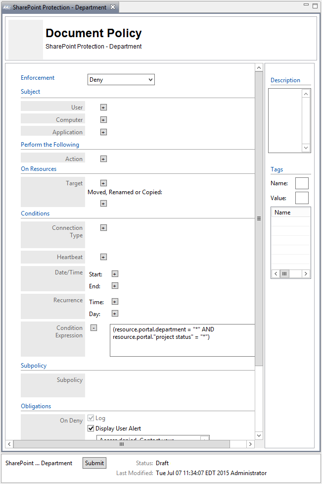
To deploy this policy, follow the steps in Section 8.4.5.
8.4.4.2.2. Defining a Department-based Sub-policy that Enforces an Allow Decision when Certain Conditions are met
In the Policies panel in the top-left corner of the main Policy Studio window, click on your new policy to highlight it. Then click on New Policy to create a sub-policy.
Select a name for the new sub-policy then click OK.
In the policy editing panel, make the following edits:
From the Enforcement drop-down menu, select Allow.
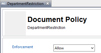
In the On Resources area, click on the plus sign box next to Target.
In the Components panel, click on Resources, then the Portals tab to see the components you created earlier.

From the Portals tab, left-click and hold the **Project status =
any** component and drag it onto the Target field.
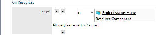
In the Conditions area, in the Condition Expression text box, enter the ACPL:
(user.department = resource.portal.department OR (user.department = “Business Intelligence” AND (resource.portal.department = “Marketing” OR resource.portal.department = “Sales”)))
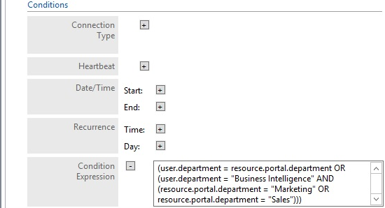
In the Policy Editing panel, your policy should look like this:

To deploy this policy, follow the steps in Section 8.4.5.
8.4.4.3. Defining a Sensitivity-based Policy Set
In order to define a sensitivity-based policy set, follow instructions similar to defining the department-based policy set in Section 8.4.4.2:
8.4.4.3.1. Defining the Top-level Sensitivity Policy that Enforces a General Deny Decision
In the Policies panel in the top-left corner of the main Policy Studio window, click on your folder to highlight it. Then click on New Policy.
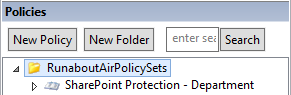
In the Create New Policy window, enter a name for the new policy. From the Policy Type drop-down menu, select Document Policy (which applies to all SharePoint policies). Click OK.
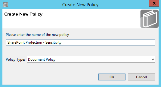
The new policy opens automatically in an editing panel. For this policy, keep the default Deny enforcement. Make these edits:
In the On Resources area, click on the plus sign box next to Target. This automatically populates in and Resource Component.
In Condition Expression enter the ACPL: resource.portal.sensitivity > “0”
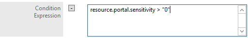
In the Obligations area, check the Display User Alert box in order to customize the deny message displayed to the user when access is denied.
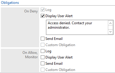
In the policy editing panel, your policy should look like this:
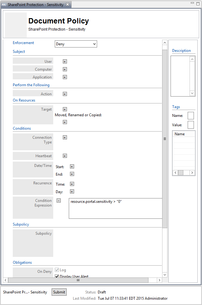
To deploy this policy, follow the steps in Section 8.4.5.
8.4.4.3.2. Defining a Sensitivity-based Sub-policy that Enforces an Allow Decision when Certain Conditions are met for Access to Sensitivity Level 1 Documents
Similar to the steps in Section 8.4.4.2.2 for creating the Department-based sub-policy, do the following:
In the Policies panel in the top-left corner of the main Policy Studio window, click on your new policy to highlight it. Then click New Policy to create a sub-policy.
Select a name for the new sub-policy then click OK.
In the policy editing panel, make the following edits:
From the Enforcement drop-down menu, select Allow.
In the Subject area, click on the plus sign next to User.
In the Components panel in the bottom-left corner of the Policy Studio window, click on Subjects, then the Users tab to see the components you created earlier.
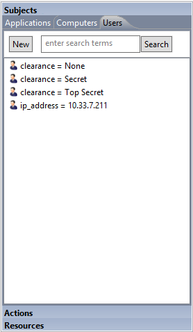
Left-click and hold the clearance = None component to drag it onto the User field.
Left-click and hold the clearance = Secret component to drag it onto the User field.
Left-click and hold the clearance = Top Secret component to drag it onto the User field.
In the On Resources area, click on the plus sign box next to Target.
- In the Components panel in the bottom-left corner of the Policy Studio window, click on Resources, then the Portals tab to see the components you created earlier.
- Left-click and hold the sensitivity = 1 component to drag it onto the Target field.
In the policy editing panel, your policy should look like this:
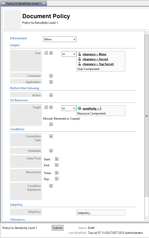
To deploy this policy, follow the steps in Section 8.4.5.
8.4.4.3.3. Defining a Sensitivity-based Sub-policy that Enforces an Allow Decision when Certain Conditions are met for Access to Sensitivity Level 2 Documents
Similar to the steps in Section 8.4.4.3.2 for creating the sensitivity-based sub-policy for sensitivity level 1 documents, do the following:
In the Policies panel in the top-left corner of the main Policy Studio window, click on your new policy to highlight it. Then click New Policy to create a sub-policy.
Select a name for the new sub-policy then click OK.
In the policy editing panel, make the following edits:
From the Enforcement drop-down menu, select Allow.
In the Subject area, click on the plus sign next to User.
In the Components panel in the bottom-left corner of the Policy Studio window, click on Subjects, then the Users tab to see the components you created earlier.
Left-click and hold the clearance = Secret component to drag it onto the User field.
Left-click and hold the clearance = Top Secret component to drag it onto the User field.
In the On Resources area, click on the plus sign box next to Target.
- In the Components panel in the bottom-left corner of the Policy Studio window, click on Resources, then the Portals tab to see the components you created earlier.
- Left-click and hold the sensitivity = 2 component to drag it onto the Target field.
In the Conditions area, click on the plus sign boxes next to Time and Day. Edit those fields to match below:
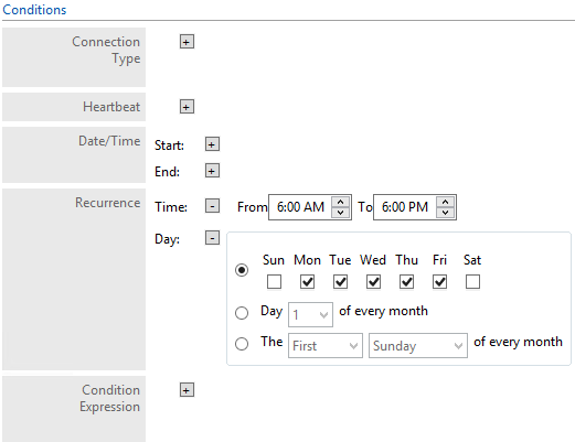
In the policy editing panel, your policy should look like this:
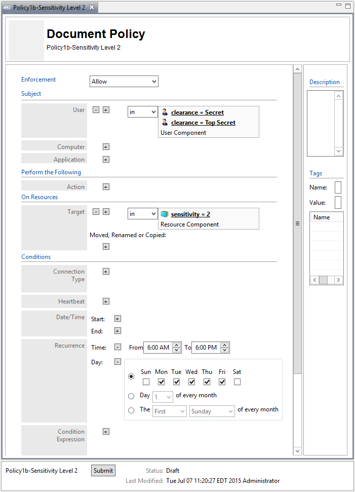
To deploy this policy, follow the steps in Section 8.4.5.
8.4.4.3.4. Defining a Sensitivity-based Sub-policy that Enforces an Allow Decision when Certain Conditions are met for Access to Sensitivity Level 3 Documents
Similar to the steps in Section 8.4.4.3.2 for creating the sensitivity-based sub-policy for sensitivity level 1 documents, do the following:
In the Policies panel in the top-left corner of the main Policy Studio window, click on your new policy to highlight it. Then click New Policy to create a sub-policy.
Select a name for the new sub-policy then click OK.
In the policy editing panel, make the following edits:
From the Enforcement drop-down menu, select Allow.
In the Subject area, click on the plus sign next to User.
In the Components panel in the bottom-left corner of the Policy Studio window, click on Subjects, then the Users tab to see the components you created earlier.
Left-click and hold the clearance = Top Secret component to drag it onto the User field.
In the On Resources area, click on the plus sign box next to Target.
- In the Components panel in the bottom-left corner of the Policy Studio window, click on Resources, then the Portals tab to see the components you created earlier.
- Left-click and hold the sensitivity = 3 component to drag it onto the Target field.
In the Conditions area, click on the plus sign boxes next to Time and Day. Edit those fields to match below:
In the policy editing panel, your policy should look like this:

To deploy this policy, follow the steps in Section 8.4.5.
8.4.4.4. Defining a Maintenance-based Policy Set
In order to define a maintenance-based policy set, follow instructions similar to defining the department-based policy set in Section 8.4.4.2:
8.4.4.4.1. Defining the Top-level Maintenance Policy that Enforces a General Deny Decision
In the Policies panel in the top-left corner of the main Policy Studio window, click on your new folder to highlight it. Then click New Policy.
In the Create New Policy window, enter a name for the new policy. From the Policy Type drop-down menu, select Document Policy (which applies to all SharePoint policies). Click OK.
The new policy opens automatically in an editing panel. For this policy, keep the default Deny enforcement. Make these edits:
- In the On Resources area, click on the plus sign box next to Target. This automatically populates in and Resource Component.
- In Condition Expression, enter the ACPL: resource.portal.maintenance = “*”
- In the Obligations area, check the Display User Alert box in order to customize the deny message displayed to the user when access is denied.
In the policy editing panel, your policy should look like this:
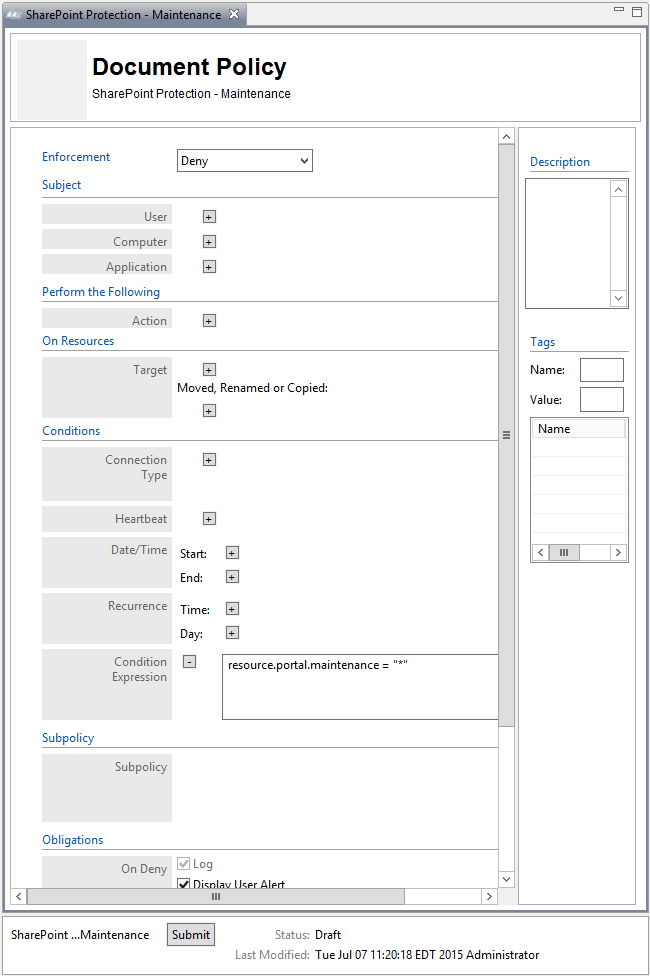
To deploy this policy, follow the steps in Section 8.4.5.
8.4.4.4.2. Defining a Maintenance-based Sub-policy that Enforces an Allow Decision when Certain Conditions are met for Access to Documents whose Maintenance Attribute is defined as Yes
Similar to the instructions in Section 8.4.4.2.2 for defining a Department-based sub-policy, do the following:
In the Policies panel in the top-left corner of the main Policy Studio window, click on your new policy to highlight it. Click New Policy to create a sub-policy under this main policy.
Select a name for the new sub-policy, then click OK.
In the policy editing panel, make the following edits:
From the Enforcement drop-down menu, select Allow.
In the On Resources area, click on the plus sign box next to Target.
- In the Components panel in the bottom-left corner of the Policy Studio window, click on Resources, then the Portals tab to see the components you created earlier.
- Left-click and hold the maintenance = yes component to drag it onto the Target field.
In the Conditions area, click on the plus sign boxes next to Time and Day. Edit those fields to match below:
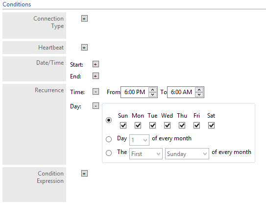
In the policy editing panel, your policy should look like this:
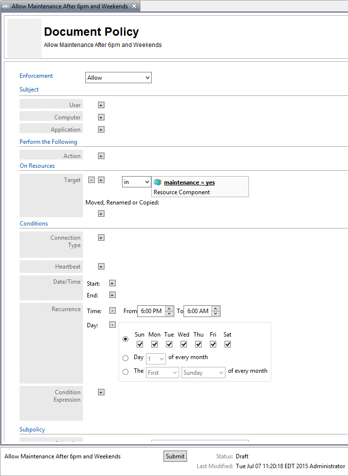
To deploy this policy, follow the steps in Section 8.4.5.
8.4.4.4.3. Defining a Maintenance-based Sub-policy that Enforces an Allow Decision when Certain Conditions are met for Access to Documents whose Maintenance Attribute is defined as No
Similar to the instructions in Section 8.4.4.2.2 for defining a Department-based sub-policy, do the following:
In the Policies panel in the top-left corner of the main Policy Studio window, click on your new policy to highlight it. Click New Policy to create a sub-policy.
Select a name for the new sub-policy, then click OK.
In the policy editing panel, make the following edits:
From the Enforcement drop-down menu, select Allow.
In the On Resources area, click on the plus sign box next to Target.
- In the Components panel in the bottom-left corner of the Policy Studio window, click on Resources, then the Portals tab to see the components you created earlier.
- Left-click and hold the maintenance = no component to drag it onto the Target field.
In the policy editing panel, your policy should look like this:
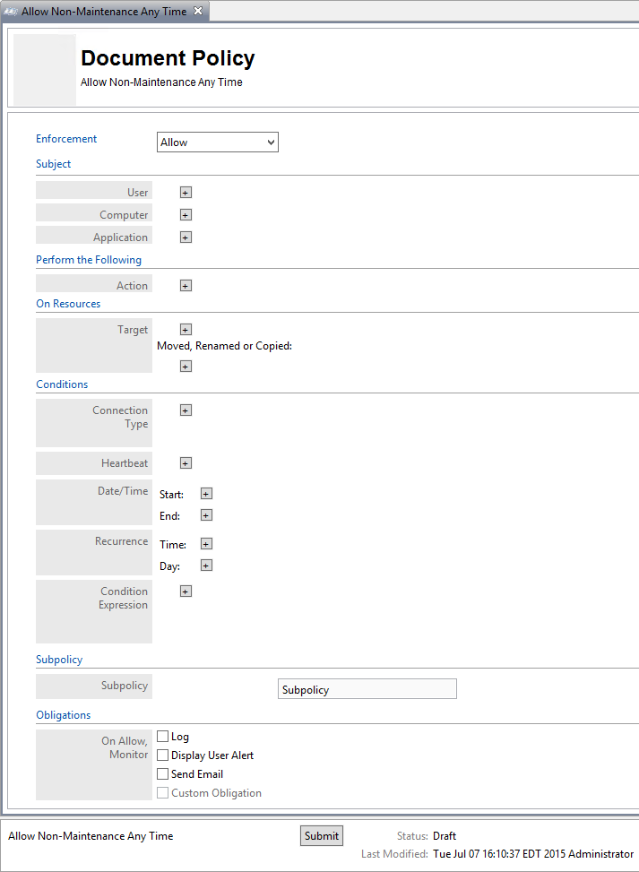
To deploy this policy, follow the steps in Section 8.4.5.
8.4.4.5. Defining an IP Address-based Policy Set
In order to define an IP address-based policy set, follow instructions similar to defining the department-based policy set in Section 8.4.4.2.
8.4.4.5.1. Defining the top-level IP Address Policy that Enforces a General Deny Decision
In the Policies panel in the top-left corner of the main Policy Studio window, click on your new folder to highlight it. Then click New Policy.
In the Create New Policy window, enter a name for the new policy. From the Policy Type drop-down menu, select Document Policy (which applies to all SharePoint policies). Click OK.
The new policy opens automatically in an editing panel. For this policy, keep the default Deny enforcement. Make these edits:
In the Condition Expression, enter the ACPL: resource.portal.sensitivity = “*”
In the Obligations area, check the Display User Alert box in order to customize the deny message displayed to the user when access is denied.
In the policy editing panel, your policy should look like this:

To deploy this policy, follow the steps in Section 8.4.5.
8.4.4.5.2. Defining an IP Address-based Sub-policy that Enforces an Allow Decision for Access to Resources at any Sensitivity Level when a User does not come from an Environment with a Restricted IP Address (ex: 10.33.7.211)
Similar to the instructions in Section 8.4.4.2.2 for defining a Department-based sub-policy, do the following:
In the Policies panel in the top-left corner of the main Policy Studio window, click on your new policy to highlight it. Click New Policy to create a sub-policy.
Select a name for the new sub-policy, then click OK.
In the policy editing panel, make the following edits:
From the Enforcement drop-down menu, select Allow.
In the On Resources area, click on the plus sign box next to Target.
- In the Components panel in the bottom-left corner of the Policy Studio window, click on Resources, then the Portals tab to see the components you created earlier.
- Left-click and hold the sensitivity = 1 component to drag it onto the Target field.
In the policy editing panel, your policy should look like this:
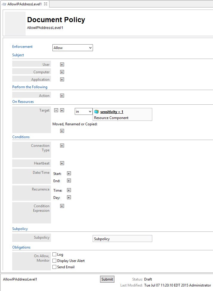
To deploy this policy, follow the steps in Section 8.4.5.
8.4.4.5.3. Defining an IP Address-based Sub-policy that Enforces an Allow Decision for Access to Resources at Only Sensitivity Level 1 when a User comes from an Environment with a Restricted IP Address (ex: 10.33.7.211)
Similar to the instructions in Section 8.4.4.2.2 for defining a Department-based sub-policy, do the following:
In the Policies panel in the top-left corner of the main Policy Studio window, click on your new policy to highlight it. Then click New Policy to create a sub-policy.
Select a name for the new sub-policy, then click OK.
In the policy editing panel, make the following edits:
From the Enforcement drop-down menu, select Allow.
In the Subject area, click on the plus sign box next to User.
From the drop-down menu, select not in.
In the Components panel in the bottom-left corner of the Policy Studio window, click on Subjects, then the Users tab to see the components you created earlier.
- Left-click and hold the ip_address=10.33.7.211 component to drag it onto the User field.
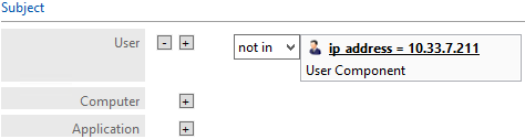
In the On Resources area, click on the plus sign box next to Target.
- In the Components panel in the bottom-left corner of the Policy Studio window, click on Resources, then the Portals tab to see the components you created earlier.
- Left-click and hold the sensitivity = 1 component to drag it onto the Target field.
- Left-click and hold the sensitivity = 2 component to drag it onto the Target field.
- Left-click and hold the sensitivity = 3 component to drag it onto the Target field.
In the policy editing panel, your policy should look like this:
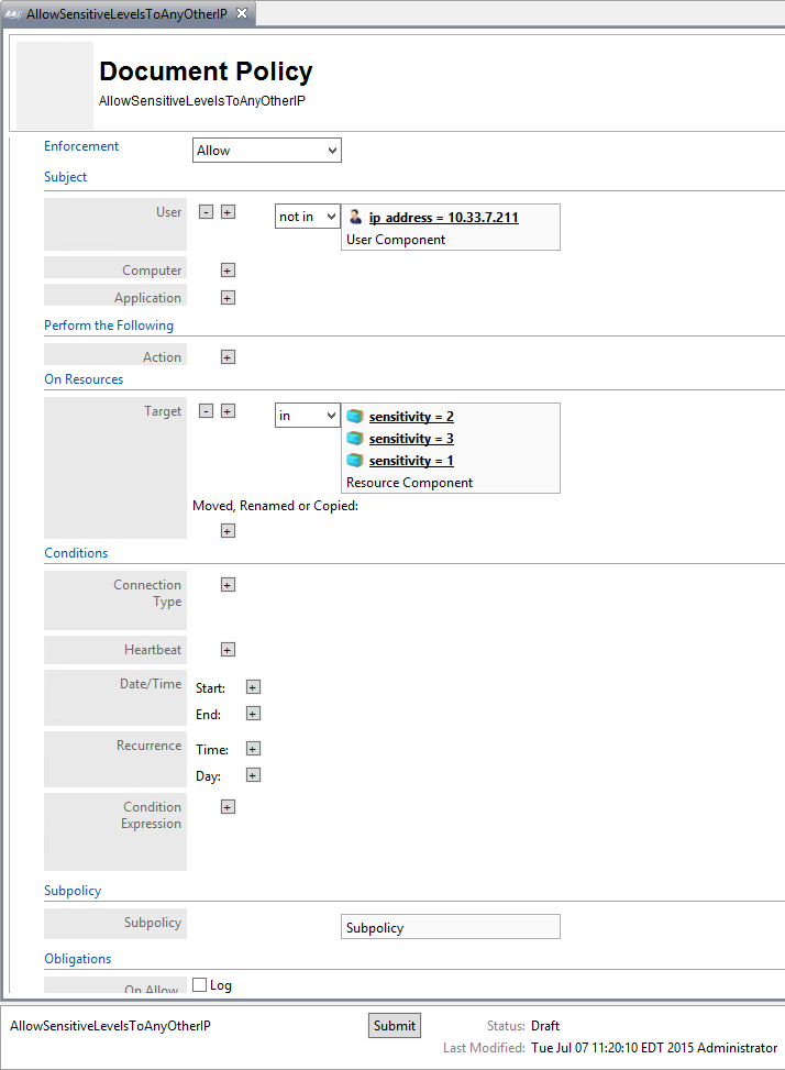
To deploy this policy, follow the steps in Section 8.4.5.
8.4.5. Deploying Policy
In order to deploy policies, follow steps similar to those for deploying a component (see Section 8.4.3.2.1.1):
In the Policies panel in the top-left corner of the main Policy Studio window, click on the policy you want to deploy. In the policy editing panel, click Submit.
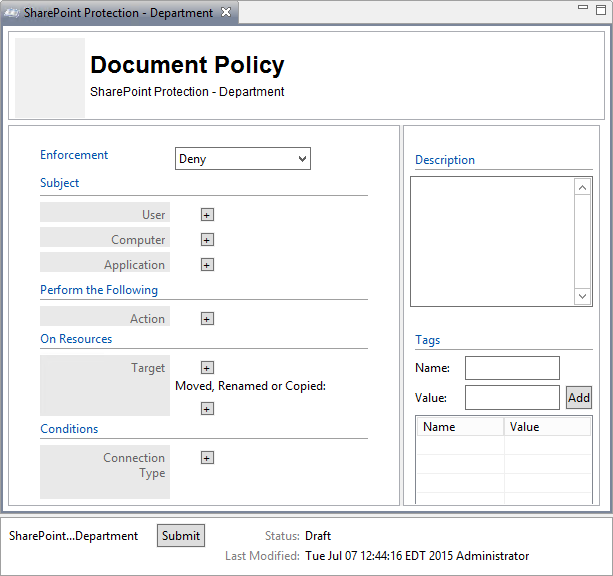
Or, in the Policies panel in the top-left corner of the main Policy Studio window, right-click the policy you want to deploy. Select Submit from the floating menu.
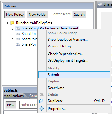
In the Submit window, click Submit.

From the component editing panel, note the differences. The new status reads Submitted for Deployment. Click Deploy.
Or, in the Policies panel in the top-left corner of the main Policy Studio window, right-click the policy you want to deploy. Select Deploy from the floating menu.
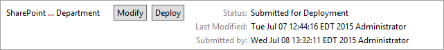
In the Deploy window, click OK. Note: You may specify to deploy immediately, which we choose in our example. You may also deploy at the following day at midnight, or at a different specific date and time.
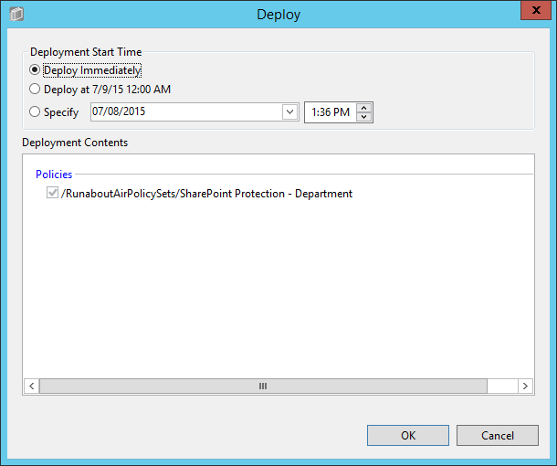
At the bottom of the policy editing panel, verify that the Status is now Pending Deployment. This will remain for the duration of the heartbeat (described in Section 7).
After the duration of the heartbeat has passed, Status should read as Deployed. This indicates that the component is actively deployed in your ABAC system.
8.4.6. Modifying and Re-Deploying Policies and Components
In order to modify existing policies and re-deploy them, do the following:
8.4.6.1. Modifying and Deploying Existing Policies
In the Policies panel in the top-left corner of the main Policy Studio window, click on the policy you want to modify. In the policy editing panel, click Modify.
- Or, right-click the policy you want to modify and select Modify from the floating menu.
In the policy editing panel, make the desired changes and click Submit.
Follow the deploy instructions from Section 8.4.5 to deploy the modified policy.
8.4.6.2. Modifying and Deploying Existing Components
In the Components panel in the bottom-left corner of the main Policy Studio window, click on the component you want to modify. In the policy editing panel, click Modify.
- Or, right-click the component you want to modify and select Modify from the floating menu.
In the component editing panel, make the desired changes and click Submit.
Follow the deploy instructions from Section 8.4.5 to deploy the modified component.
8.4.7. Deactivating Policies and Components
8.4.7.1. Deactivating Policies
In the Policies panel in the top-left corner of the main Policy Studio window, right-click the policy you want to deactivate. Select Deactivate from the floating menu.
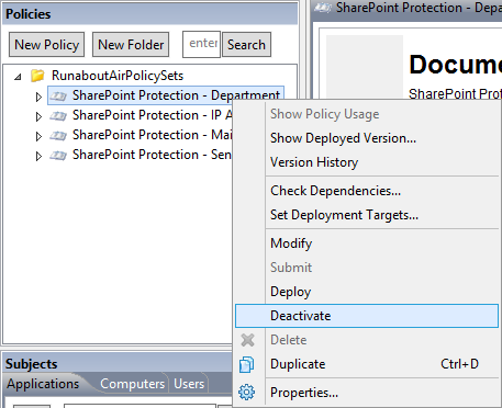
At the bottom of the policy editing panel, note the change in Status to Pending Deactivation. Click Deploy.
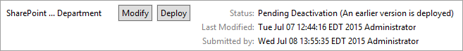
In the Deploy window, click OK. Note: You may specify to deploy immediately, which we choose in our example. You may also deploy the following day at midnight, or at a different specific date and time.
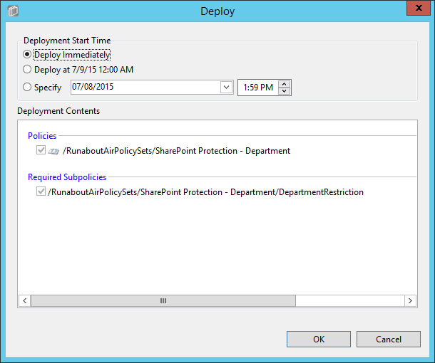
Verify at the bottom of the policy editing panel that the Status is now Pending Deactivation. This will remain for the duration of the heartbeat (described in Section 7).
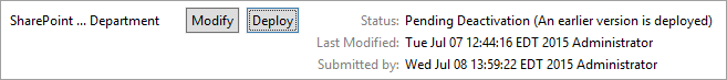
After the duration of the heartbeat has passed, Status should read as Inactive. This indicates that the component is currently inactive in your ABAC system.
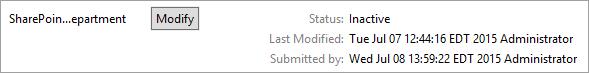
8.4.7.2. Deactivating Components
- In the Components panel in the bottom-left corner of the main Policy Studio window, right-click on the component you want to deactivate. Select Deactivate from the floating menu.
- Follow steps 2-5 in Section 8.4.7.1 for deactivating policies.
8.4.8. Deleting Policies and Components
Note: In order to delete a policy or component, you must first deactivate the item and any related sub-items.
8.4.8.1. Deleting Policies
In the Policies panel in the top-left corner of the main Policy Studio window, right-click on the policy you want to delete. Select Delete from the floating menu.
In the Delete window, click Yes.
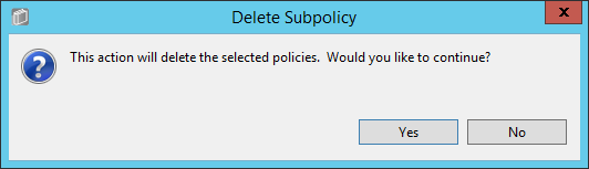
8.4.8.2. Deleting Components
- In the Components panel in the bottom-left corner of the main Policy Studio window, right-click on the policy you want to delete. Select Delete from the floating menu.
8.5. Configuring Attributes in NextLabs
Section 6 illustrated how to configure the attribute flow between several of the servers and components in the ABAC architecture. Note that the NextLabs Entitlement Manager was installed on the SharePoint Server, which is where all of the activity in Section 8.5 occurs.
In order to configure NextLabs to enforce policy on all of the attributes coming from the front-channel as SharePoint Claims, you must first stop the NextLabs Policy Controller service, edit the configuration.xml file in the SharePoint Enforcer software architecture, restart Internet Information Services (IIS), then restart the NextLabs Policy Controller service using the following instructions.
8.5.1. Stopping the NextLabs Policy Controller Service
On the SharePoint Server, click the Windows icon and begin typing the word Services.
Double-click on the icon to open the Services application.
Within the Services application window, in the list of services, click on the Name column to sort by alphabetical order, and look for Control Center Enforcer Service.
If the status of the Control Center Enforcer Service is Running, stop it.
Click the Windows icon.
Double-click the Stop Policy Controller shortcut icon.
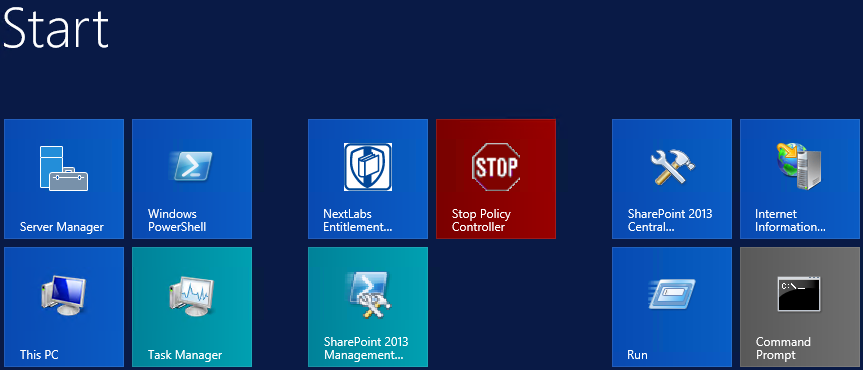
Enter your NextLabs Administrator credentials. Then click Stop.
In the Stop Enforcer Service success window, click OK.
8.5.2. Editing the Configuration File
8.5.2.1. Locating and Opening the SharePoint Enforcer configuration.xml File
In Windows Explorer, find and open the SharePoint Enforcer configuration.xml file.
Double-click the C:/ drive.
Double-click Program Files.
Double-click NextLabs.
Double-click SharePoint Enforcer.
Double-click config.
Right-click Configuration.xml to edit the file in a text editor.
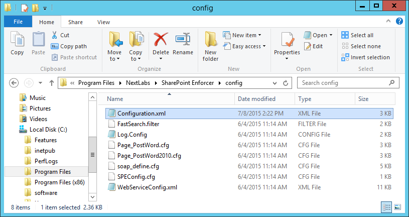
8.5.2.2. Configuring Resource Attributes from SharePoint Metadata
Within the configuration.xml file, look for the <SPEConfiguration> tag.
Under that tag, but above a <User Attribute> tag, insert tags for each site-level or sub-site level resource attribute of interest.
For example, in our build we created policies based on the department resource attribute, so in our configuration.xml file we included the following:
<PropertyBag disabled="false" level="SiteCollection">
     <Property disabled="false" name="department" attributename="department" />
</PropertyBag>
<PropertyBag disabled="false" level="SubSite">
     <Property disabled="false" name="department" attributename="department" />
 </PropertyBag>
From the example above, the top of the configuration.xml file looks like this:
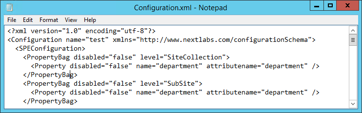
8.5.2.3. Configuring User Attributes from SharePoint Claims
Within the configuration.xml file directly under any <PropertyBag> closing tags, find the <User Attribute> </User Attribute> portion of the document. Initially, its default contents in that area may look like this, containing some default user attributes such as “emailAddress” or “adfsGroup”:
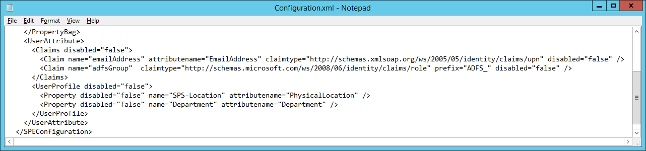
In the User Attribute area, add more claims here to include all the attributes you will be expecting to evaluate in NextLabs policies for access control decisions.
For example, in our build we created policies based on users’ “clearance”, “department”, and “ip_address”, so in our configuration.xml file we included the following, among others:
<Claim name="department" attributename="department" claimtype="http://schemas.xmlsoap.org/ws/2005/05/identity/claims/department" disabled="false" />
<Claim name="ip_address" attributename = "ip_address" claimtype="http://schemas.xmlsoap.org/ws/2005/05/identity/claims/ip_address" disabled="false" />
<Claim name="clearance" attributename = "clearance" claimtype="http://schemas.xmlsoap.org/ws/2005/05/identity/claims/clearance" disabled="false" />
From the example above, the rest of our configuration.xml file looks like this:
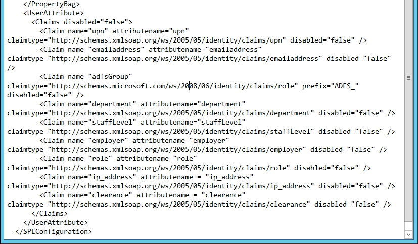
8.5.2.4. Saving Changes to the Configuration File
From the File menu, click Save, or Ctrl+S on your keyboard.
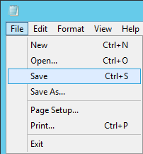
8.5.3. Restarting IIS via Windows PowerShell
Click the Windows icon.
In the Search text box, begin typing PowerShell.
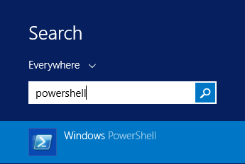
Click on Windows PowerShell.
In the PowerShell window, type the command: iisreset. Press Enter.

In the PowerShell window, verify that services stopped and restarted successfully.
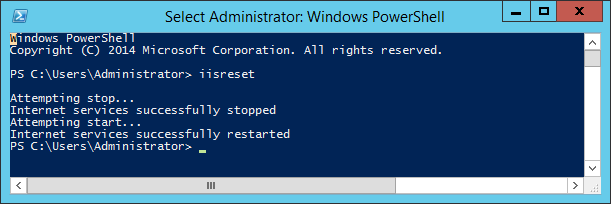
8.5.4. Restarting the NextLabs Policy Controller Service
Click on the Windows icon and begin typing the word Services.
Double-click the Services icon to open the application.
Within the Services application window in the list of services, click on the Name column to sort by alphabetical order and look for Control Center Enforcer Service.
Right-click Control Center Enforcer Service and click Start.
- It may be necessary to click the Refresh icon in order to see the Control Center Enforcer Service status change to Running.
8.6. Functional Test
8.6.1. Updated Bin File After Policy Creation/Modification
After a policy or component is deployed for the first time, or modified and re-deployed within Policy Studio on the SQL Server, an encrypted bundle.bin file on the SharePoint Server will be updated after one heartbeat. As explained in Section 7, on the SharePoint Server it is the responsibility of the Controller Manager component of the NextLabs Policy Controller (PDP) to encrypt the bundle.bin file on the local file system for use during policy evaluation by the PDP.
To ensure the policy logic is being correctly sent from the NextLabs Policy Studio (PAP) on the SQL Server to the bundle.bin file on the SharePoint Server for use by the NextLabs Policy Controller (PDP), you can find the bundle.bin file and decrypt its contents to see your policy logic decrypted there.
8.6.1.1. On the SharePoint Server Note Timestamp of the Bundle.bin File and Decrypt Its Contents
Double-click the C:/ drive.
Double-click Program Files.
Double-click NextLabs.
Double-click Policy Controller.
Scroll down to find bundle.bin and note the timestamp in the Date Modified column. This would be the last time policies or components were deployed.
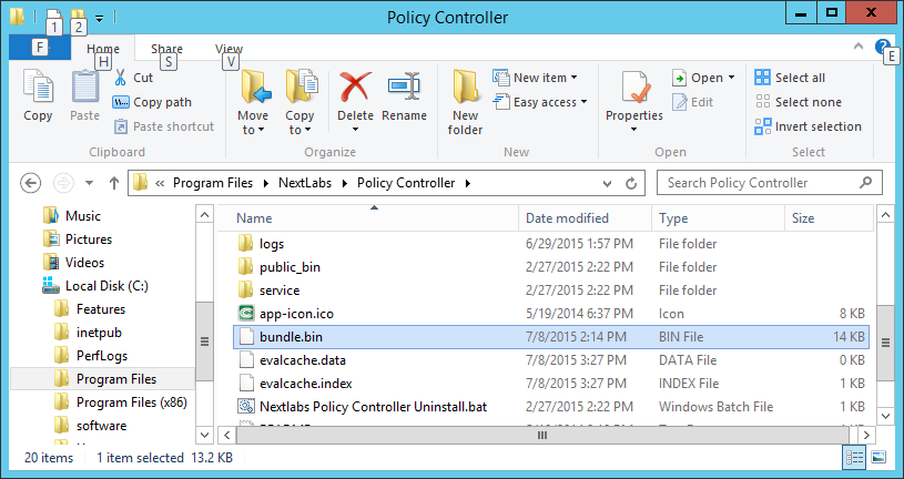
Scroll back up and double-click on the bin folder.
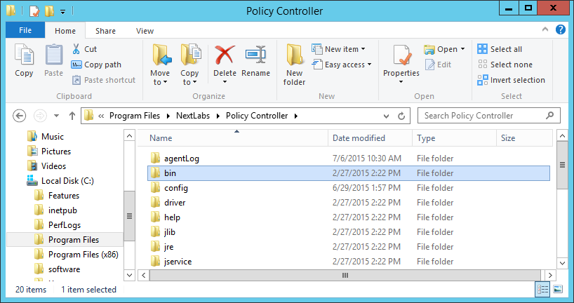
Scroll down to find Decrypt.exe.
In the Decrypt window, enter the administrator’s Password and press Enter.
After the Decrypt window disappears, click on Policy Controller to return to that folder. Scroll down and double-click the bundle.out file.

In the text editor window, scroll down to find policies that you have created previously. Example: RunaboutAirPolicySets/SharePoint Protection – Department top-level policy
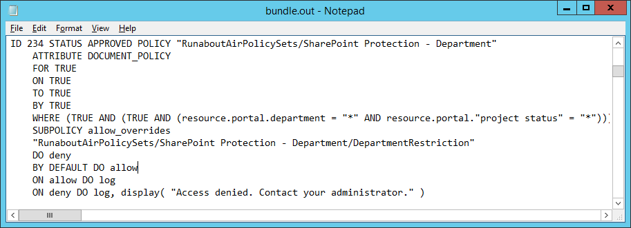
8.6.2. Reviewing NextLabs AgentLog to Illustrate History of Access Control Evaluations during SharePoint Access
Double-click the C:/ drive.
Double-click Program Files.
Double-click NextLabs.
Double-click Policy Controller.
Double-click AgentLog.
Right-click the Agento.log.0 locked file and select Copy.
Within the agentLog folder, right-click in an empty space and select Paste.
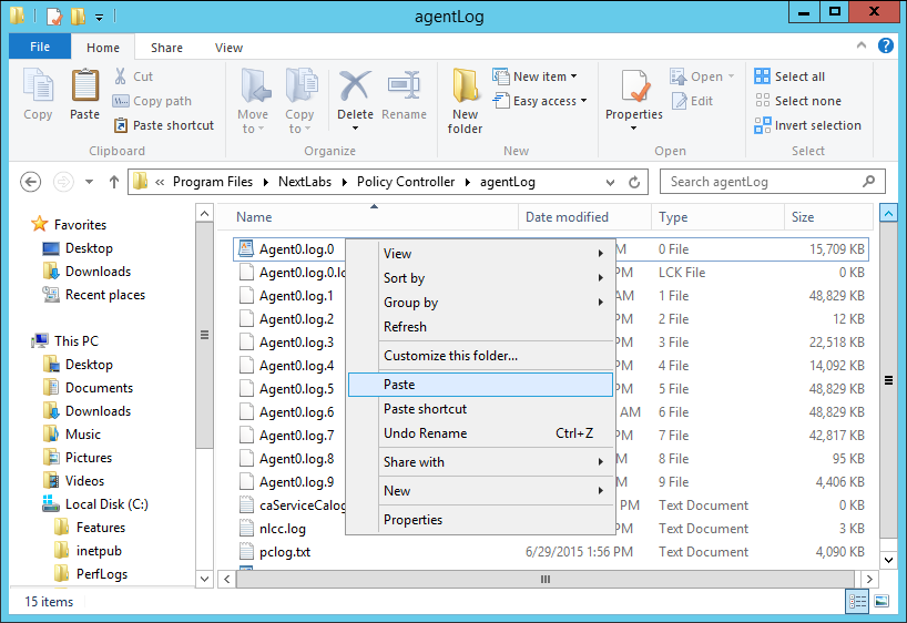
Double-click the Agent0.log-Copy.0 file to view its contents.
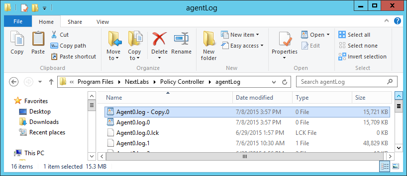
Scroll down to view the contents. You can press Ctrl+F to find keywords such as any identifying word from your policy definitions, words common to ABAC activity such as allow or deny, or words native to NextLabs logging such as effect =.
Examples of information found in this Agent0.log-Copy.0 file:
All of the policies evaluated during one instance of access:
Jul 7, 2015 4:29:53 PM com.bluejungle.pf.engine.destiny.f performContentAnalysis
FINEST: No from resource found.  Ignoring
Jul 7, 2015 4:29:53 PM com.bluejungle.pf.engine.destiny.EvaluationEngine evaluate
INFO: Matching policies for 2342972204282387:
X: RunaboutAirPolicySets/SharePoint Protection - Department/DepartmentRestriction
A: RunaboutAirPolicySets/SharePoint Protection - Department
X: RunaboutAirPolicySets/SharePoint Protection - IP Address/AllowIPAddressLevel1
X: RunaboutAirPolicySets/SharePoint Protection - IP Address/AllowSensitiveLevelsToAnyOtherIP
A: RunaboutAirPolicySets/SharePoint Protection - IP Address
X: RunaboutAirPolicySets/SharePoint Protection - Maintenance/Allow Maintenance After 6pm and Weekends
A: RunaboutAirPolicySets/SharePoint Protection - Maintenance/Allow Non-Maintenance Any Time
A: RunaboutAirPolicySets/SharePoint Protection - Maintenance
X: RunaboutAirPolicySets/SharePoint Protection - Sensitivity/Policy1a-Sensitivity Level 1
X: RunaboutAirPolicySets/SharePoint Protection - Sensitivity/Policy1b-Sensitivity Level 2
X: RunaboutAirPolicySets/SharePoint Protection - Sensitivity/Policy1c-Sensitivity Level 3
A: RunaboutAirPolicySets/SharePoint Protection – Sensitivity
An allow decision was evaluated when this example user, Jorge
Gonzalez, logged into the Runabout Air SharePoint:
Jul 7, 2015 4:29:53 PM com.bluejungle.destiny.agent.controlmanager.PolicyEvaluatorImpl queryDecisionEngine
INFO: Request 2342972204282387 input params
  to
  application
        pid: 5140
  environment
        request_id: 2342972204282387
        time_since_last_successful_heartbeat: 31
  host
        inet_address: 184536844
  operating-system-user
        id: S-1-5-21-972639958-268376111-2639239546-1138
  action
        name: OPEN
  sendto
  from
        title: relying party inc - root site
        ce::id: sharepoint://sharepoint.abac.test/
        name: relying party inc - root site
        sub_type: site
        type: site
        ce::destinytype: portal
        url: sharepoint://sharepoint.abac.test/
  user
        :
        id: S-1-5-21-972639958-268376111-2639239546-1138
        title: Scientist
        department: Research and development
        stafflevel: Senior
        upn: jgonzalez@ABAC.TEST
        company: Conway
        name: abac\jgonzalez
        clearance: Top Secret
  Ignore obligation = false
  Process Token = 984
  LogLevel = 3
  Result: Effect = allow (total:4608ms, setup:4605ms, obligations:0ms)
  Obligations:
  From file list: [sharepoint://sharepoint.abac.test/]
  To filename list: null
9. Leveraging NextLabs Control Center Reporter for Reporting and Auditing Purposes
9.1. Introduction
In previous sections of this How-To Guide (Section 7), we installed several NextLabs products that can be used to define and deploy Attribute Based Access Control policies and enforce decisions regarding user access to Microsoft SharePoint resources based on user, object, environmental attributes, and the corresponding policies in place. We also illustrated how to use and configure the NextLabs Policy Studio, the product responsible for Policy Lifecycle Management, and discussed policy strategy and the translation of business logic into policy (Section 8).
In this section of the How-To Guide, we will illustrate how to use the NextLabs Control Center Reporter, a component of the previously installed NextLabs Control Center (Section 7), in order to generate reports and provide a graphical user interface for prior policy evaluation and access control decisions in your environment.
Reporter is automatically installed during the NextLabs Control Center installation, which was detailed in Section 7. In this How-To section, we will introduce Reporter, its purpose, interface, and capabilities, then illustrate some example uses based on our build.
9.1.1. Components Used in this How-To Guide
NextLabs Control Center Reporter v7.5.0 (64) – web application and graphical user interface for evaluating prior policy evaluation access control decisions and generating reports for monitoring and auditing.
9.1.2. Pre-requisites to Complete Prior to this How-To Guide
If you intend to do a setup without identity federation and federated logins, you must:
If you intend to incorporate a trust relationship between an IdP and RP and use federated logins into SharePoint, you must:
- Install and configure Active Directory (see Section 2)
- Setup and configure the RP and IdP (see Section 3)
- Install and configure Microsoft SharePoint (see Section 4)
- Configure the SharePoint federated login with the RP (see Section 5)
- Configure the attribute flow between all endpoints (see Section 6)
- Install and configure NextLabs Control Center, Policy Studio, and Policy Controller (see Section 7)
- Define and deploy policies based on your business rules (see Section 8)
9.2. Introduction to NextLabs Control Center Reporter
The NextLabs Control Center Reporter is a web application that can be used to generate reports on how information is being used in your environment. You can use Reporter to define and run custom queries about policy enforcement activities that are recorded in the Activity Journal, a native, automatic logging mechanism built into the NextLabs SQL database that was configured during installation of the NextLabs Control Center (Section 7). These queries are referred to as reports. Reports can be designed to answer a wide variety of questions, such as who has access to certain documents, who is using which resources and when, what types of policy enforcement is taking place, what activity occurred within a given department, and so on.
In addition to reports, you can also use Reporter to create monitors that trigger alerts when specified policy enforcement criteria are met. You can design monitors to cover a wide range of scenarios, such as sending an alert through email when access to a certain resource has been denied more than a specified number of times in a given time period; or when the volume of classified documents that have been downloaded in a given time period exceeds a specific file size. Together, monitors and alerts can provide continuous coverage of critical policy enforcements in an enterprise, as well as a notification system that lets you know when action is required.
Reporter is intended for use by whoever is responsible for monitoring and reporting on compliance, gathering statistics about document usage, and investigating any suspected incidents of information mishandling. This may include administrators, IT staff, managers, executives, and auditors, or any other authorized personnel.
User permissions are defined in the Administrator application (another component of Control Center installed in Section 7), by creating a new User and assigning one of the four available roles to it. By default, all roles include permission to open and use the reporting functionality of Reporter.
9.2.1. Opening Reporter
On the server where NextLabs Control Center was installed, open a web browser (i.e., SQL Server in this build).
Enter the URL and press Enter: https://<hostname>/reporter, i.e., https://localhost/reporter
At the Reporter login screen, enter valid credentials, such as the Control Center Administrator account created in Section 7. Click Login.
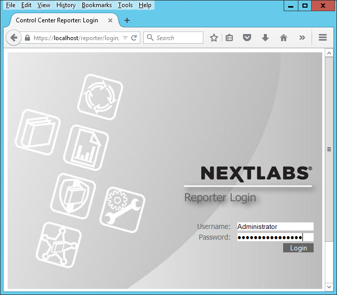
In your browser, the Reporter opening view defaults to the Dashboard tab. The Dashboard tab, Reports tab, and Monitoring tab will be discussed more thoroughly in subsequent sections of this How-To Guide.
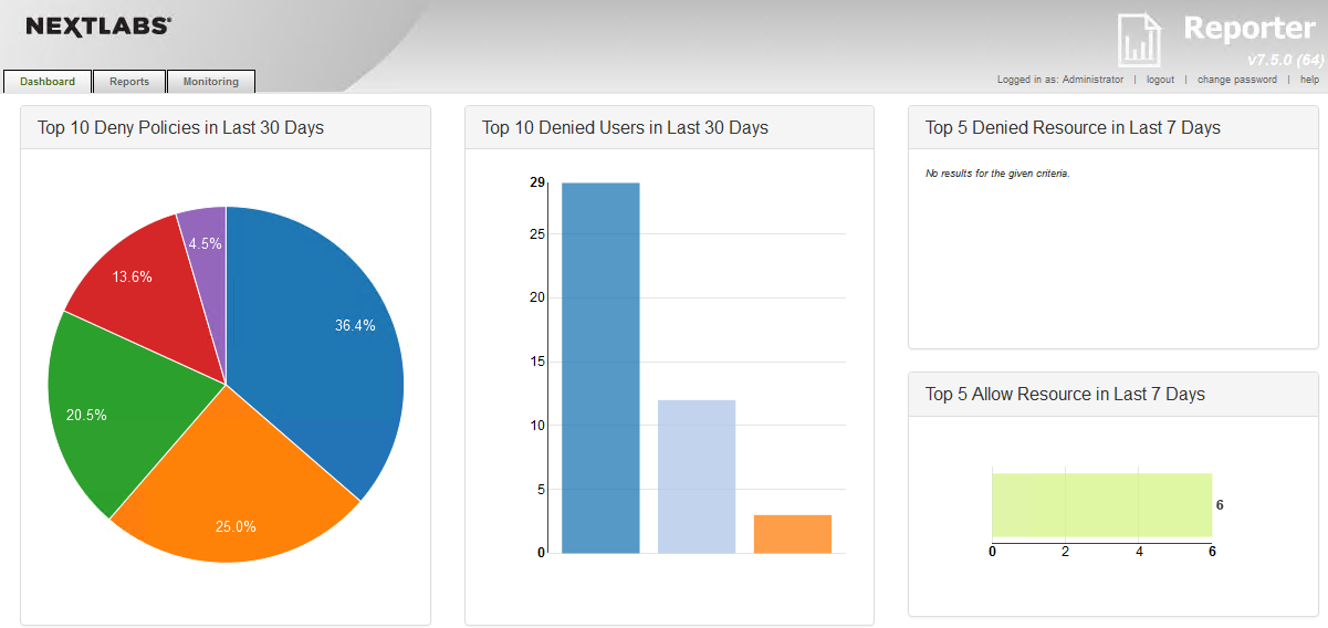
9.3. Introduction to Reporter Dashboard
The Reporter Dashboard is divided into panes, each displaying a predefined statistical view of data that provides a snapshot of policy enforcement trends. In the default configuration of Reporter, these panes display data in the following graphs (from the NextLabs Control Center Reporter User Guide, available only to customers at this time):
| Graph | Description | May Indicate |
|---|---|---|
| Top Five Deny Policies (Month) | Pie chart representing the five Deny policies that were most frequently enforced over the previous thirty days. |
|
| Top Ten Denied Users (Month) | Bar chart representing the ten users who have had the most instances of any Deny policy enforced against them. |
|
| Top Five Deny Resources (Week) | Bar chart representing the five resources that any users have most frequently attempted to access and been blocked by an active policy, over the previous seven days. |
|
| Top Five Allow Resources (Week) | Bar chart representing the five resources that users have most frequently attempted to access and been allowed by an active policy, over the previous seven days. |
|
| Deny Policy Enforcement Trends (Month) | Bar chart representing the trend, over the previous 30 days, of the daily total instances of any deny policy being enforced on any user, for any resource. |
|
| Recent Allows | List of details about the most recent ten instances of any allow policy being enforced against any user, for any resource. Details listed include:
|
|
| Recent Denys | List of details about the most recent ten instances of any deny policy being enforced against any user, for any resource. Details listed include:
|
|
| Alerts this Week: Group by Tags | Treemap representing volume of alerts in the current week. Alerts are grouped by monitor tags. |
|
| Today’s Alerts: Details | List of details about the alerts raised in the current day. Details include:
|
|
These panels are configurable such that an administrator can choose which panels and data are visible and how they are laid out within the Dashboard according to the business’s business logic, policies, and priorities.
The data displayed in all panes of the dashboard is refreshed from the Activity Journal each time you open the Dashboard tab. This means that data is updated on demand; for example, if a pane shows some statistic for the past week, that reflects not the last seven whole calendar days, but the last seven 24-hour periods starting from the top of the current hour.
9.3.1. Exploring the Dashboard
On the server where NextLabs Control Center was installed, open a web browser, i.e., SQL Server in this build
Enter the URL and press Enter: , i.e., https://localhost/reporter
At the Reporter login screen, enter valid credentials such as the Control Center Administrator account created in Section 7. Click Login.
In your browser, the Reporter will default to the Dashboard tab.
The charts and graphs on the Dashboard are interactive. When you move your cursor over a bar in a bar chart or a slice in the pie chart, a tooltip displays information about that value series.
Example seen in the image below: 36.4% of the Deny policies evaluated in the last 30 days belonged to the SharePoint Protection – Department policy set.
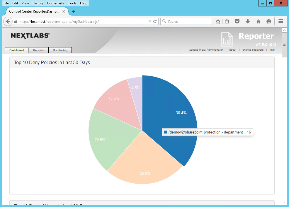
Another example from this build seen in the image below: in the Deny Policies trend in the last 30 days, June 26, 2015 saw an unusually large number of Deny Policies relative to other days.
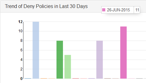
9.4. Introduction to Defining and Running Custom Reports in Reporter
In Reporter, you can define and run reports in the Reports tab. This tab is divided into two panes, Saved Reports on the left side of the Reports tab window and Report Details on the right.
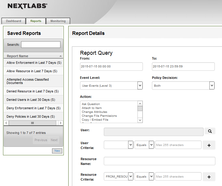
The Saved Reports pane provides a list of all saved reports available to you. This includes all reports you create and save, all reports saved by other users and marked as Shared, and the sample reports used to generate data that is displayed in the Dashboard tab. When you click on any item in Saved Reports, the details of that report are displayed in Report Details on the right. This is also where you work when you create a new report.
In the Report Details pane, define the following:
- the time period of the policy activity data to cover in the report
- the criteria, or filters, that determine what policy activity data to include in the report
- the output format of the report
The default settings in Report Details display when you click the Reports tab or when you click New in the Saved Reports pane. By default, the time period for the report is the current day, all policy activity data at the user level is included, and the data is presented in table format.
After defining a new report or editing an existing report, click Run at the bottom of the Report Details pane to view the results, which we will illustrate in the following two subsections.
9.4.1. Defining a Custom Report
In this subsection, we will list the standard steps for creating a custom report. In Section 9.5 of this How-To Guide we will illustrate some example custom report sections that demonstrate Reporter’s report capabilities.
9.4.1.1. Logging into Reporter
Before being able to define a custom report, you must first log in to Reporter and click on the Reports tab as seen in the steps below:
On the server where NextLabs Control Center was installed in Section 7, open a web browser, i.e., SQL Server in this build.
Enter the URL and press Enter: https://<hostname>/reporter, i.e., https://localhost/reporter
At the Reporter login screen, enter valid credentials, such as the Control Center Administrator account created in Section 7. Click Login.
In your browser, the Reporter user interface will default to the Dashboard tab. The Dashboard tab, Reports tab, and Monitoring tab will be discussed more thoroughly in subsequent sections of this How-To Guide.
Click on the Reports tab to open the Reports tab window.
9.4.1.2. Defining the Custom Report
In order to define a custom or new report, you must specify filters and change default settings within the Report Details – Report Query pane. If you don’t specify any filters or change any of the default settings, the report retrieves all policy activity data categorized as user-level events for the current day.
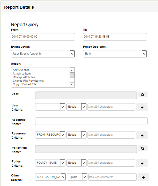
In the Report Details - Report Query pane, define the report query by filling in data or using drop-down menus to define your desired report.
Note: Many of the fields are optional. Required fields contain default values.
In the From and To fields, specify the start date and time, and end date and time, respectively, of the time period you want the report to cover. Click in the field to choose a date and time from the calendar. When specifying a report period, be sure to consider the time zone where Control Center is installed, and the time period of data stored in the Activity Journal.
In Event Level, select the level of event verbosity the report contains:
User Events (default): Logged in the Activity Journal as Level 1
Application Events (application and user-level events): Logged in the Activity Journal as Level 2
All System Events (system, application, and user-level events): Logged in the Activity Journal as Level 3
Note: As a rule, you should leave this setting at User Events. This setting significantly reduces the amount of system noise. Application- or system-level events generally are not useful in monitoring policy or user activities.
In Decision, select the type of enforcement effect to include in this report:
- Allow: Instances when the policy permitted the user to perform the action covered by the policy. Note that the report results always depend on what information is logged. If the policy does not have any On Allow logging obligation specified, this report will not return any On Allow data whether or not you select this option.
- Deny: Instances when the policy did not allow the user to perform the action. Deny decisions are always logged.
- Both: All instances when the policy was enforced, with either Allow or Deny effect.
In Action, select the user action or actions to include in this report. The list shows all currently defined actions.
To select multiple actions, hold Ctrl and click each action. If you do not make any selections, all actions are included.
Note: Policies involving Paste actions do not support logging obligations, therefore, instances of their enforcement are not included in reports.
In User, specify one or more users on which to filter the activity data, or leave this field blank to include all users. Use the User Lookup window (magnifying glass icon) to browse through all users currently defined in your Information Network Directory, and select the users you want.
In User Criteria, specify additional user criteria by creating one or more conditions. Each condition consists of a user attribute, an operator, and a value. You must click the + button to add a condition to the query.
In Resource Path, type the network path of the resource on which to filter, or leave this field blank to include all resources.
In Resource Criteria, specify additional resource criteria by creating one or more conditions. Each condition consists of a resource attribute, an operator, and a value. Click the + button to add a condition to the query.
In Policy Name, specify one or more policies on which to filter, or leave this field blank to include all policies. Use the Policy Lookup window to browse through and select which policies you want to include.
In Policy Criteria, specify additional policy criteria by creating one or more conditions. Each condition consists of a policy attribute, an operator, and a value. Click the + button to add a condition to the query.
In Other Criteria, specify additional criteria by creating one or more conditions. Each condition consists of a general attribute (for example, host name, host IP, and application name), an operator, and a value. Click the + button to add a condition to the query.
9.4.1.3. Setting the Custom Report Display Options
Within the Report Details – Report Query pane, directly below the Other Criteria filter, continue with these steps to set the display options for your custom report:
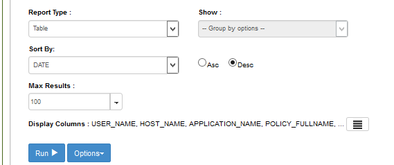
In Report Type, select the output format in which to display the data: Table, Bar Chart, Horizontal Bar Chart, or Pie Chart. Use a table to display policy activity details in a row-and-column format. Use a chart to display a summary of policy activities.
If you selected one of the charts in Report Type, in Show, select a grouping option. Grouping is not available to a table.
- Group by User: The chart shows the number of enforcement events for each user covered by the report.
- Group by Resource: The chart shows the number of enforcement events for each resource covered by the report.
- Group by Policy: The chart shows the number of enforcement events for each policy covered by the report.
- Group by Month: The chart shows the number of enforcement events for each month covered by the report. Select this option only if the time period you specified spans more than one month.
- Group by Day: The chart shows the number of enforcement events for each day covered by the report.
In Sort By, select a field on which to sort the data, then select Asc to sort in ascending order or Desc to sort in descending order. If the report is a table, you can sort the data by any attribute. If the report is a chart, you can sort either by the grouping item (user, resource, policy, month, or day) or by Result Count (the number of enforcement events for each user, resource, policy, month, or day).
In Max Results, specify the maximum number of results to display in the table or chart. For charts, this number represents the maximum number of bars in a bar chart, or slices in a pie chart. For readability reasons, charts should display a limited number of bars or slices. For a table, the number represents the maximum number of rows (each row represents an event). Tables that show a large number of rows present the data on multiple pages.
In Display Columns, select the columns to display in a table. This setting applies to tables only. USER_NAME, POLICY_FULLNAME, POLICY_DECISION, HOST_NAME, and APPLICATION_NAME are selected by default. To remove any of those columns or to add other columns, click
 and use the arrow icons to move columns out of, or
into, the Selected pane.
and use the arrow icons to move columns out of, or
into, the Selected pane.
9.4.2. Running a Custom Report
Directly beneath the filters and data fields for defining the report and setting its display settings, do the following in order to run the report and/or save it for the future:
At the bottom of the Report Details – Report Query pane, click Run to generate the new report.
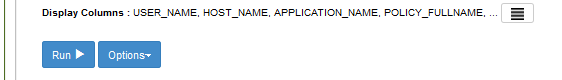
If you want to run this report again in the future, save the report. Click Options, and select Save.
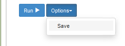
9.5. Example Custom Report and Available Formats
In this section, we will present examples of different report formats, all representing a small set of event data, returned by the same custom report from our build. By comparing the example formats, you will gain a better understanding of the way the different formats can be used to highlight different aspects of the same data depending on your business rules or priorities.
The custom report used in this section will result from a query that requests all events by users on all resources for one week (June 7, 2015 to June 13, 2015). We include columns that are relevant for our example business logic and the ABAC policies we put in place in Section 8. For example, we chose to include the “Department” and “Sensitivity” columns, which were custom attributes in the metadata we added to the documents uploaded to the RP’s SharePoint sites.
9.5.1. Defining the Example Custom Report
9.5.1.1. Customizing Report Query Fields for this Report
In the Report Query pane, change the fields for the From and To date to match the desired query for the week of June 7, 2015 to June 13, 2015.
In the Report Query pane, click on the Max Results field to open the drop-down menu. We chose 11 for demonstration purposes.
In the Report Query pane, leave the rest of the fields in the default query settings.
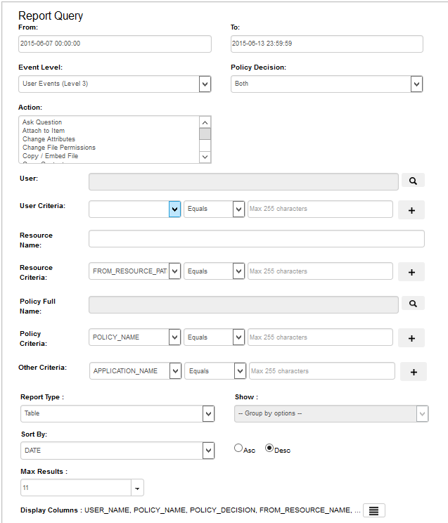
9.5.1.2. Editing the Columns for Custom Views
Toward the bottom of the Report Query pane, click on the columns icon at the end of the Display Columns line of text to open the Select Display Column window.
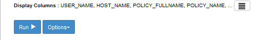
In the Select Display Column window, in the Available attribute list, review standard attributes (i.e. Action, Log_Level, Host_IP, etc) and custom attributes (department, sensitivity).
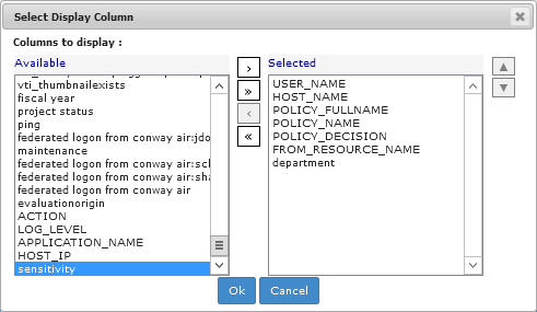
Click on any available attribute of interest to highlight it, then click the single right arrow button
 to add it to the list
of Selected attributes.
to add it to the list
of Selected attributes.The attribute name will move from the Available list to the Selected list.
Note: Attributes can be added and removed individually by using the single arrow buttons between lists, or as a group by using the double arrow buttons between lists.
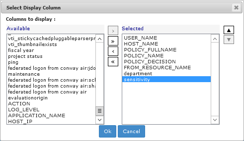
9.5.1.3. Running the Report Query
At the bottom of the Report Query pane, click Run to run the query. (Tip: You can click on Options and Save or Save As to save the query for future use.)
Scroll down in your browser window to see the Results pane illustrated in the following section.
9.5.2. Format: Table of Event Data
The default results pane with the display columns you selected displays showing the query results. This is illustrated in the following image.
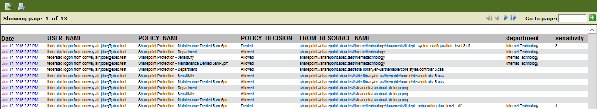
This excerpt from the query results shows that:
13 pages of policy enforcement events were logged.
All events in this excerpt occurred on June 12, 2015 (as illustrated in the Date column).
Each event from this excerpt was triggered by the same user, who had logged in with a federated identity from the IdP (Sections 2 through 5)
Each event corresponds to one of three policies: SharePoint Protection – Sensitivity, SharePoint Protection – Maintenance Denied 5am-5pm, or SharePoint Protection – Department.
Five resources were involved:
- The first row shows that the resource was an .rtf document from the Internet Technology department’s SharePoint sub-site, marked at sensitivity level 3.
- The second through fourth rows show that the resource was the Internet Technology department site.
- The fifth through seventh rows show that the resources were the underlying .css style sheet and logo used on the SharePoint site.
- The seventh through tenth rows (up to the second to last) show that the resources were the underlying .css style sheet and logo used on the SharePoint site.
- The eleventh and final row from this excerpt shows that the resource was another .rtf document from the Internet Technology department SharePoint sub-site, marked at sensitivity level 1.
In the case of three out of the five resources, the enforcement decision was Allow, as shown in the fourth column (second through tenth rows).
In the case of two out of the five resources, the enforcement decision was Deny, as shown in the fourth column (first and last rows).
Keep these details in mind as you analyze the data in the following charts.
9.5.3. Format: Bar Chart Grouped by Policy Chart
Grouping events by policy is useful for identifying policies that are being triggered with unexpected frequency, which may be an indication that they are improperly designed and cover users, resources or actions that they should not. It can also indicate concentrated efforts at unauthorized data access. To examine the latter possibility, it is often helpful to switch to the Group by User option in order to focus on who is performing the activity, as seen in Section 9.5.2.
9.5.3.1. Customizing the Display Settings
Using the Report Details – Report Query window from Section 9.5.2 for displaying the results in Table format, make the following edits to display results in a Bar Chart grouped by Policy:
From the Report Type list, select Bar Chart.
From the Show list, select Group by Policy
From the Sort By list, select Policy.
From the Max Results list, choose a number or type one in the field.
Example: The value 6 means that our bar chart will display up to six policies, including but not limited to the number of policies displayed in the Table format.
Click on the Asc (Ascending) radio button to set the sorting order.
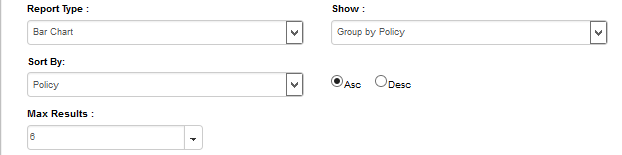
9.5.3.2. Running the Report Query
At the bottom of the Report Query pane, click Run to run the query
9.5.3.3. Viewing the Results as a Bar Chart Grouped by Policy
In the same browser window, scroll down if necessary. Under the Run button, review the resulting Bar Chart Grouped by Policy.
As illustrated below, hundreds of enforcement decisions were logged during the week, and the three most commonly evaluated policies include two that were included in the table from Section 9.5.2, formatting results by Table.
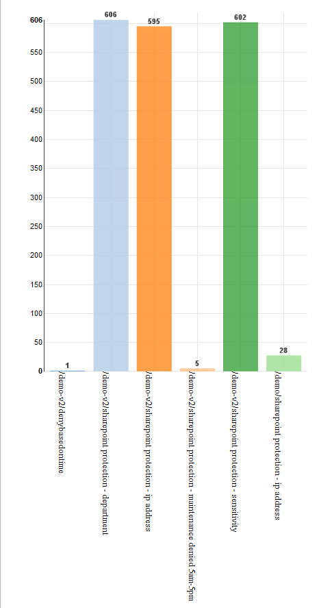
9.5.4. Format: Bar Chart Grouped by User Chart
When the same data is grouped by user, and the bar chart is selected, the following chart is generated. As noted previously, the four policies were each triggered by a different user, so the graph shows four bars—each representing one user. Each is labeled with a user name. In this example, the bars are the same height, since each of the four users triggered a policy once.
9.5.4.1. Customizing the display settings
Using the same Report Details – Report Query window from the previous subsection, make the following edits to display results in a Bar Chart Grouped by Policy.
From the Report Type list, select Bar Chart.
From the Show list, select Group by User.
From the Sort By list, select User.
From the Max Results list, choose a number or type one in the field.
Example: The value 6 indicates that this will be the maximum number of users reflected in our Bar Chart.
Leave Asc selected.
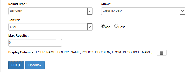
9.5.4.2. Running the Report Query
At the bottom of the Report Query pane, click Run to run the query.
9.5.4.3. Viewing the Results as a Bar Chart Grouped by User
In the same browser window, scroll down if necessary. Under the Run button, review the resulting Bar Chart Grouped by User:
As illustrated below, only five users were accessing the protected RP SharePoint resources during this week period, and all logged in via federated identity from the IdP.
- Two users had very minimal activity logged during this week: schen@abac.test and sharepointadmin@abac.test
- Two users had relatively similar activity logged during this week: jdoe@abac.test and jgonzalez@abac.test
- One user had an extremely large amount of activity logged during this week: lsmith@abac.test
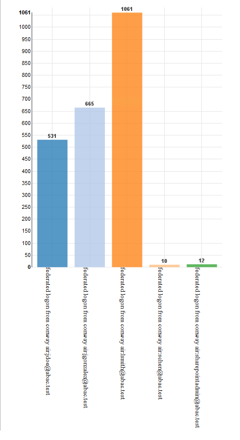
9.5.5. Format: Pie Chart Grouped by Resource
The Group by Resource option shows the extent of specified events—in this case, policies being triggered—per individual resource covered by the report.
Because policies often cover large numbers of individual documents or other resources, grouping by resource is only helpful when the number of events has already been narrowed down to a smaller set by various report filters, such as policies or users. A pie charts is ideal here, because in the context of resource use, the relative access activity regarding some single file or other resource as compared to all others is generally of more interest than any absolute number of instances of access.
9.5.5.1. Customizing the Display Settings
Using the same Report Details – Report Query window from the previous subsection, make the following edits to display results in a Bar Chart grouped by Policy
From the Report Type list, select Pie Chart.
From the Show list, select Group by Resource.
From the Sort By list, select Resource.
From the Max Results list, select a number or type one.
Example: The value 10 means that will be the maximum number of resources displayed in our Pie Chart.
Leave Asc selected.
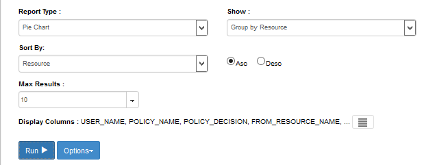
9.5.5.2. Running the Report Query
- At the bottom of the Report Query pane, click Run to run the query.
9.5.5.3. Viewing the Results as a Bar Chart Grouped by User
In the same browser window, scroll down if necessary. Under the Run button, review the resulting Bar Chart Grouped by Policy:
As illustrated below, the maximum of ten resources are displayed in the pie chart.
- The most commonly accessed resource during this week period (69.5%) was our build’s SharePoint home page.
- The two second-most accessed resources during this week period were the ABAC IT department and its forms sub-site (where documents are stored).
- The remaining seven most-accessed resources during this week after the top three have relatively very minimal access, and the majority of those are documents that belong to specific department sub-sites, such as Finance Dept Quarterly Reports, IT Dept System Configuration documents, etc.
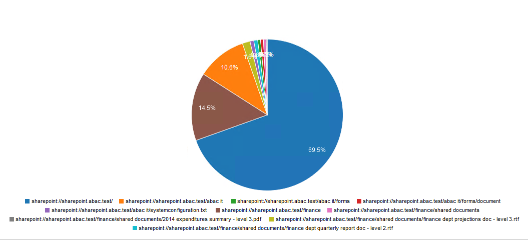
9.6. Further Example Custom Reports from Our Build
In this section, we will illustrate how to define custom reports that will provide a graphical representation of particular kinds of activity that could be of interest to our RP business.
For our first additional example, we will use a fictitious user from our build’s IdP and check her activity on the RP SharePoint site within a specific time period. The report we define will focus on the user Lucy Smith (username: lsmith) and all of her Allowed and Denied access during a specific timeframe, such as May 1, 2015 – June 30, 2015.
For our second additional example, we will use a document on the RP SharePoint site that has been marked with a metadata attribute called sensitivity. The document’s sensitivity value is set to 3, which according to our example ABAC policies requires that 1) the user accessing the document belongs to the same or appropriate department for accessing it, 2) the access occurs during regular business hours Monday-Friday, and 3) the user has a clearance attribute value of Top Secret. The report we define will focus on the access attempts on that document for the months of May and June 2015.
9.6.1. Custom Report Illustrating All Access for One User During a Two-Month Period
Follow the steps for Section 9.5.4, Format: Bar Chart Grouped by User, and change the From field to May 1, 2015 and the To field to June 30, 2015.
Within the browser, in the results area at the bottom of the Report Details window, click on the vertical bar that represents the user lsmith@abac.test or abac\lsmith (light green, the far-right bar in our chart below).
The Report window of your browser will automatically refresh, and a default query on the User will run automatically.
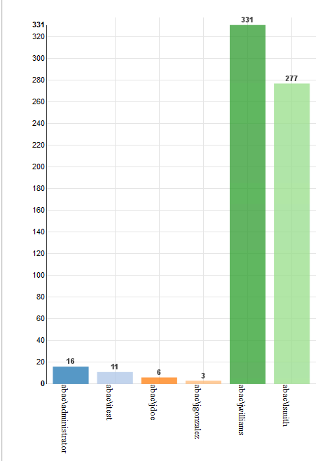
Within the browser window, scroll up to Report Details and verify that the User: field was automatically populated with abac\lsmith.
In the Report Query pane, you will see that the default query pertaining to the User has a Report type of Table, sorted by date in descending order, with a maximum of 100 results.
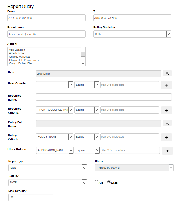
Within the browser window, scroll back down to the resulting Table to review its data. See the excerpt below.
If desired, you can change the Display Columns, Report Type, etc. to customize your view as illustrated in previous subsections.
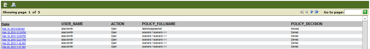
9.6.2. Viewing Access Attempts on Individual Resources
This section provides instructions for creating a custom report that shows the access attempts of a single resource for a period of two months.
Follow the steps for Section 9.5.5, Format: Pie Chart Grouped by Resource, and change the From field to May 1, 2015 and the To field to June 30, 2015.
From the resulting list of resources under the pie chart, find the color of a resource with a name including level 3, which according to our schema means in SharePoint metadata the sensitivity level attribute is equal to 3.
Click on that resource in the pie chart (example: light pink area of 2.3% is for a Sales Dept document called sales document 2015 – level 3.txt).
This will begin an automatic default query for that resource similar to the one done above based on the user lsmith.

Within the browser window, scroll up to Report Details and verify that the Resource Name: field was automatically populated with the name Sales document 2015 – level 3.txt.
In the Report Query pane, you will see that the default query pertaining to the resource has a Report type of Table, sorted by date in descending order, with a maximum of 100 results.
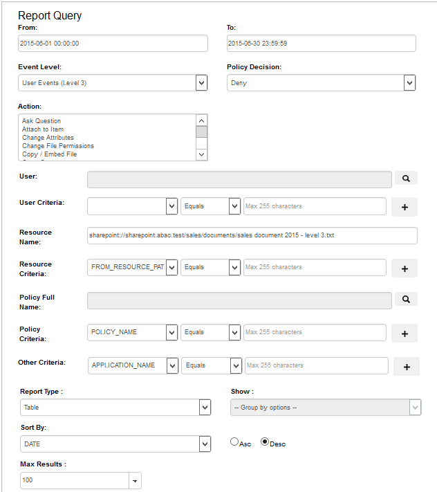
Within the browser window, scroll back down to the resulting table to review its data. See the excerpt below.
If desired, you can change the Display Columns, Report Type, etc. to customize your view as illustrated in previous subsections.

10. Configuring a Secondary Attribute Provider
10.1. Introduction
This section provides a description of the architecture, compilation, and deployment instructions for a secondary attribute provider and its components, which we describe as a custom Policy information point (PIP), to be included as part of the ABAC infrastructure. We also demonstrate how to configure the Relying Party server to accommodate the custom PIP and its component JIT provisioning mechanism.
The secondary attribute provider comes into the picture when a user tries to access a resource at the Relying Party’s Resource Provider, and the Policy decision point (PDP) finds that an essential attribute needed to make the access control decision is missing from the initial set of attributes sent from the Identity Provider. In our build, this would mean a user with a federated identity (via PingFederate Identity Provider, IdP, augmented with two-factor authentication by RSA AA) has already logged into Microsoft SharePoint (Relying Party’s Resource Provider), but when trying to open a particular resource on the site, the NextLabs Policy Controller (PDP) makes a run-time decision that additional subject attributes are needed before the access decision can be made. The PDP determines this while evaluating the existing ABAC policies (created in the NextLabs Policy Studio, PAP in our ABAC build) against the user, resource, and environmental attributes at play at the time of requested access.
Providing the secondary attribute collection capability in our build required the implementation of new components and related features, which we will describe more in detail later in the section:
- NextLabs Policy Information Point (PIP) Plugin to extend the NextLabs Policy Controller (PDP) when additional attribute(s) are needed
- Protocol broker to initiate and receive a SAML attribute query and SAML response
- Custom data store plugin for PingFederate on the Relying Party (RP) server which will cache attributes in order to limit the number of secondary requests to the PingFederate Identity Provider (IdP) server
- Apache Directory Server (ApacheDS), an LDAP in which PingFederate can create and update local user accounts and associated attributes based on the attributes contained in SAML assertions received after authentication from IdP
- PingFederate RP configuration must be modified so that it can serve as an IdP as needed, such as when checking its JIT cache (Apache DS LDAP) before sending requests to the IdP
In later sub-sections of this section we will discuss in detail the purpose of each of these new components and features, and how they are developed, configured, compiled, and deployed.
Note: The custom PIP we have developed involves new custom components, open source components, and commercially available components. For open source and commercial components, the related descriptions in this section have been limited to installation and relevant configuration required for the desired functionality of our build. If you are interested in other details or additional capabilities of this software, explore the referenced product literature or contact that organization.
10.1.1. Pre-Requisites
In order to follow the instructions of this How-To section, it is necessary that seven of the previous How-To sections have been successfully completed. The required components that must be installed and configured before continuing in this How-To section include:
- Installation and Configuration of Active Directory (Section 2)
- Installation and Configuration of RSA AA (Section 2)
- Installation and Configuration of RSA AA Plugin (Section 2)
- Installation and Configuration of PingFederate on both the RP and IdP federation servers (Section 2 and Section 3),
- Installation and Configuration of Microsoft SharePoint (Section 4 and Section 5)
- Configuration of the attribute flow (Section 6)
- Installation and Configuration of NextLabs Control Center, Policy Studio, Policy Controller, and Entitlement Manager for SharePoint Server (Section 7)
10.1.2. Criteria for Secondary Attribute Collection
At the time of ABAC policy evaluation, required attributes may not be available or the system may not find it appropriate to use for various reasons, including, but not limited to:
- For security and privacy purposes it is not ideal to acquire all known attributes for a subject when the session is created. Some attributes maybe PII or of higher sensitivity and should not be sent to the relying party until an access request made by the user requires those attributes.
- Depending on the longevity of a session, attributes risk becoming stale. Because of this potential for staleness, it is essential to procure attributes as needed, depending on the freshness criteria established by the system. The freshness of attributes is sometimes guided by the policies established for a local cache.
- The attribute needed for a specific attribute request may not an attributed owned by the Identity provider but rather may need to be acquired from an external party attribute provider.
10.1.3. Components
The custom PIP described in this section is composed of four new components and mechanisms which interact or integrate with different existing components in our ABAC build as extensions, plugins, or web applications:
- NextLabs Plugin: This plugin extends the NextLabs Policy Controller to make attributes available based on the criteria mentioned in Section 10.1.2, when the PDP determines that attribute values needed to evaluate an ABAC policy are insufficient or unavailable. Following the recommendation in the software development framework provided by NextLabs, the NCCoE implemented this PIP plugin in Java, and deployed the plugin within the NextLabs Policy Controller software architecture on the server we call SharePoint server in our build. Due to the requirements of the Policy Controller architecture, the plugin can request the values of multiple missing attributes sequentially, one at a time.
- Protocol Broker: This agent, in the form of servlet local to the NextLabs installation, is responsible for facilitating communication between the NextLabs PIP Plugin and the PingFederate RP server following an Assertion Query/Request SAML2 Profile. This web application is deployed on a tomcat server that listens on localhost( 127.0.0.1) and only communicates using https with mutual TLS. Similar to the NextLabs PIP Plugin, this component is also installed on the SharePoint server.
- Ping Custom Data store: This custom data store is an extension built using Ping SDK. It enables the RP server to query the IdP server and coordinates resulting attribute values back to the RP. When it is chained with a built-in data store to query JIT Cache (LDAP), it enables RP to provide data from and configuration to various data stores (JIT in this build). This helps the custom data store to query and coordinate the result from local JIT and remote Active Directory at the PingFederate IdP.
- Just-in-Time provisioning is a feature provided by PingFederate to store attributes of a subject for a limited time. We implemented JIT provisioning using ApacheDS. ApacheDS 2.0 is an embeddable, extendable, standards compliant, modern LDAP server written entirely in Java, and available under the Apache Software License. It also supports network protocols like Kerberos and NTP. PingFederate RP acts as an IdP for the secondary attribute provider. To fulfill in this role, the PingFederate administrative console provides mechanisms to configure SP and IdP connections. These configurations manage connection settings to support the exchange of federation-protocol messages. It also allows configuration of data stores within the connection and an attribute contract that acts as the medium to convey attribute mapping from one entity to another.
10.1.3.1. Sequence Diagram of Custom PIP Component Interactions
Figure 10‑1 Architecture
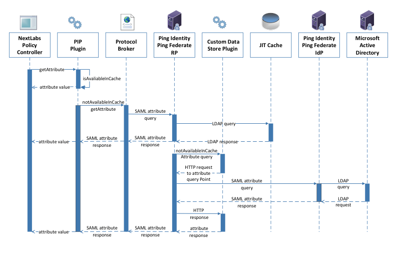
10.1.3.1.1. Description
Nextlabs PDP (Policy Controller) is the arbitrator for all access decisions at the SharePoint portal. It controls access to SharePoint URL(s) by evaluating rules against the attributes of the entities (subject and object), actions, and the environment relevant to a request. It may be possible that the attribute required for the decision is not available at run time. In that case, it looks for the registered plugin that will fetch the attribute using the following flow:
- When the policy controller does not receive the attributes required to make a decision, a secondary attribute request will be initiated by calling the PIP Plugin.
- PIP Plugin is a registered plugin with the NextLabs Policy Controller. It implements the interface dictated by the NextLabs software. By virtue of this implementation, it receives the subject and name of the attribute that is required for the policy decision.
- When the subject and attribute name are received, the PIP Plugin checks its local short-term cache (in this build, configured to hold values for two seconds) to see if the needed attribute for the subject was recently requested.
- If the attribute is still in cache, the value is returned to the Policy Controller. If the value is not in cache, the PIP Plugin initiates an HTTPS request to the Protocol Broker.
- The Protocol Broker receives the attribute name and subject from the HTTPS request and forwards them as a signed SAML 2.0 Attribute Query to PingFederate-RP on a channel protected by mutual TLS.
- Once PingFederate-RP receives the SAML 2.0 attribute query, it sends an LDAP request to the JIT cache to see if the attribute was previously queried in a secondary request.
- If the subject does not have the attribute value assigned in the JIT cache, PingFederate-RP will forward the subject and attribute name to the Custom Data Store plugin. The Custom Data Store plugin acts as a pointer back to the PingFederate-IdP. To do this, the Custom Data Store dispatches an HTTPS request to the PingFederate-RP with the PingFederate-IdP as the attribute query point.
- Ping Federate uses an HTTPS query to form a SAML 2.0 attribute query and dispatch it to the Ping Federate at the IdP.
- The Ping Federate at the IdP accepts the SAML 2.0 request, verifies if the user has the attribute of need, and replies back to the PingFederate-RP with a SAML 2.0 response.
- PingFederate-RP validates the SAML 2.0 response, retrieves attribute values, and responds to the original Custom Data Store HTTP request with the attribute values.
- The Custom Data Store then responds to the PingFederate-RP attribute request with an attribute response.
- The PingFederate-RP constructs a SAML 2.0 response and sends it to the Protocol Broker.
- The Protocol Broker retrieves the attribute or exception from the SAML 2.0 response and forwards it to the NextLabs plugin, which passes the attribute or exception back to the Policy Controller.
10.2. Component Software and Hardware Requirements
| Component | **Server where component is installed ** | Compilation method | **Required software or hardware ** | Operating System | Optional Software |
|---|---|---|---|---|---|
| Ping Custom Data Store | PingFederate RP server | Ant 1.9.2 | PingFederate 7.3.2; Java version same as PingFederate installed | Windows Server 2012 | |
| NextLabs Plugin | SharePoint server | Apache Maven 3.2.5 | SharePoint 2013; NextLabs Entitlement Manager for SharePoint Server, NextLabs Policy Controller, NextLabs Control Center, NextLabs Policy Studio; SQL Server 2012; Java version same as NextLabs Policy Controller installed (1.6) | Windows Server 2012 | BareTail (used here as a log file annotator) Copyright Bare Metal Software Pty Ltd. Download 05/22/2015. |
| Protocol Broker | SharePoint server | Apache Maven 3.2.5 | PingFederate 7.3.2; SharePoint 2013; NextLabs Entitlement Manager for SharePoint Server, NextLabs Policy Controller, NextLabs Control Center, NextLabs Policy Studio; SQL Server 2012; | Windows Server 2012 | |
| Apache Directory Server | N/A | PingFederate 7.3.2; Java 7.0 (recommended by Oracle’s JDK. Some issues have been reported with Java 8); 384 MB of memory by default, can be changed using Apache Directory Studio (included) | Windows Server 2012 |
10.3. Ping Custom Data Store
10.3.1. Functionality and Architecture
This data store was developed according to the guidelines from the Ping Identity provided here. It has three functionalities:
Configuration
- HttpConfig class is used to read in a configuration file for the custom data store. Configuration parameters, like truststore location, password and attribute names can be defined in a file and read in as a configuration by HttpConfig class. The structure of the HttpConfig class configuration is based on spring annotation.
- Other sets of configuration can be read via a web interface. A detailed description of these parameters is provided in step 9 of Section 10.3.4 in this how-to guide.
Communication
- Similarly, dispatching the http request relies on PingClient class. PingClient uses classes under the spring http package. PingClient sends an https query to Attribute Query End Point. All of the parameters for the https URL are provided by the web interface.
Custom Data Store
- CustomDataStore is a class that implements com.pingidentity.sources.CustomDataSourceDriver.
- It implements all methods specified by the contract, i.e.:
- boolean testConnection(): This method tests whether a host and port is reachable or not. It is assumed that if host and port is reachable, a URL will be available.
- java.util.List<java.lang.String> getAvailableFields():
- java.util.Map<java.lang.String,java.lang.Object> retrieveValues( java.util.Collection<java.lang.String> attributeNamesToFill, SimpleFieldList filterConfiguration)
The Class Structure and their interactions are provided in the Interaction Diagram and Class Diagram.
Figure 10‑2 Ping Custom Data Store Interaction Diagram
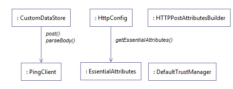
Figure 10‑3 Ping Custom Data Store Class Diagram
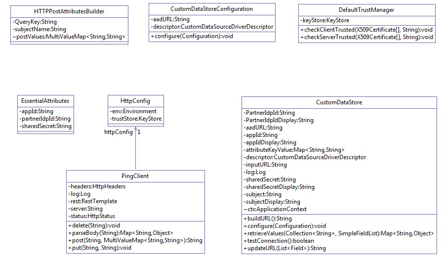
10.3.2. Deploying the Ping Custom Data Store
Note: PingFederate administrator’s manual provides detailed steps for every platform. In our build, we used the Windows Server 2012 platform.
Log on to the PingFederate RP server.
Click on the Windows icon and begin typing Services.
Double-click the Services application icon.
Click on the Name column to sort by alphabetical order, and look for PingFederateService.
If the status column reads running, right-click on PingFederateService and click Stop.
Prepare environment based on PingFederate documentation. This may involve going to ../pingfederate-7.3.0/pingfederate/sdk folder
Click on the Windows icon and begin typing Cmd.
Double-click the icon to open the Command Prompt.
In Command Prompt, navigate to your installation of PingFederate and its sdk folder by typing the following command and pressing Enter. Example:
cd C:/pingfederate-7.3.0/pingfederate/sdk/
Within the sdk folder, locate build.local.properties and open it with your default text editor. For example, enter the following command and press Enter: notepad build.local.properties
In your default text editor (Notepad in our example), set or update target-plugin.name to idp-query-data-store, i.e., # Please set the
target-plugin.nameproperty to the name of the directory (under plugin-src) that # contains the source code of the plugin you want to build.target-plugin.name=idp-query-data-store
Within the Command Prompt window, navigate to your idp-query-data-store folder by entering a cd command with a path to your idp_query_data_store and pressing Enter. Example:
cd C:/--path-to-your-idp_query_data_store
Within the Command Prompt window, copy idp-query-data-store along with all subfolders to your PingFederate installation’s sdk/plugin-src folder by entering a cp command and pressing Enter. Example:
cp –rf idp_query_data_store C:/pingfederate-7.3.0/pingfederate/sdk/plugin-src
Within the Command Prompt window, run the following command and press enter in order to make sure all relevant subfolders exist:
ls -ltr ./idp-query-data-store/
Example results from the above command:
total 4
drwxrw-r--. 3 t… t….  16 Apr 29 11:34 java
drwxrw-r--. 2 t… t…. 4096 Apr 29 12:59 lib
drwxrwxr-x. 4 t… t…. 30 May 15 17:52 build
drwxrw-r--. 2 t… t….51 May 29 09:26 conf
10.3.3. Compilation
The Building and Deploying with Ant section of the SDK Developer’s Guide by Ping provides a detailed description of compiling and deploying the project using Apache Ant. For current deployment, it may be sufficient.
Click on the Windows icon and begin typing the word Cmd.
Double-click the icon to open the Command Prompt.
It is essential to know about the attributes that this data store will return. PingFederate calls the getAvailableFields() method to determine the available fields that could be returned from a query of this data source. These fields are displayed to the PingFederate administrator during the configuration of a data source lookup. The administrator can then select the attributes from the data source and map them to the adapter or attribute contract. PingFederate requires at least one field returned from this method.
To change it, go to your ping installation directory. From that directory, navigate to ..\pingfederate-7.3.0\pingfederate\sdk\plugin-src\idp-query-data-store\conf. Open .\config.properties with your favorite editor. Change the value for the attribute called NameOfAttributes:
NameOfAttributes=fullname,username,stafflevel,role,division,employer,clearance
Use a comma to separate attribute names. More attributes can be added by adding subsequent commas and attribute names.
Navigate to your PingFederate sdk folder, i.e.,
cd C:/pingfederate-7.3.0/pingfederate/sdk/Within the Command prompt window, type the following compilation command and press Enter:
ant deploy-plugin
10.3.4. Configuration within PingFederate Administrative Console
The end of successful execution of ant deploy-plugin signals the installation of the data-store driver. Its configuration is provided in detail by Ping documentation. In summary, it spans the following process:
Logon to the Ping RP server.
Open an internet browser.
Enter the following URL and press Enter: https://localhost:9999/pingfederate/app
Enter your PingFederate administrator username and password, then click Login.
In the browser window, under the main menu area, find Server Configuration > System Settings > Data Stores. Double-click on Data Stores.

At the bottom of the browser window, click Add New Data Store.
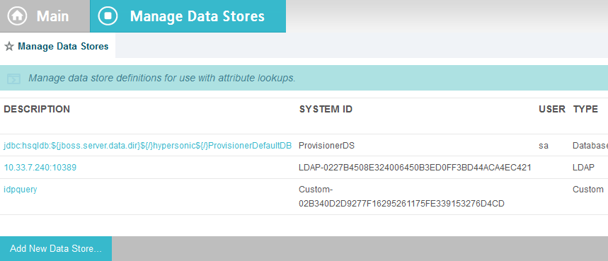
On the Data Store Type screen, select Custom and click Next.
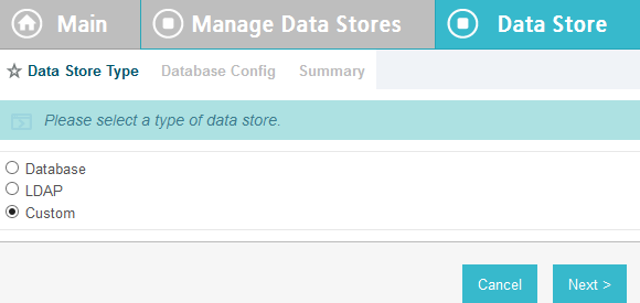
On the Custom Data Store Type screen, specify Data Store Instance Name and Data Store Type. The name can be arbitrary, but you must select IDP Attribute Query from the Data Store Type drop-down. Click Next.
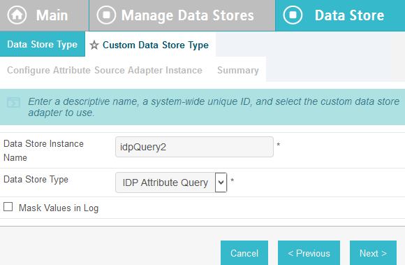
To configure the data store, the following parameters must be configured. These parameters are guided by the requirements of the end point (/sp/startAttributeQuery.ping) defined by Ping documentation here:
https://10.33.7.5:9031/sp/startAttributeQuery.ping?AppId=appid&SharedSecret=3Federate&PartnerIdpId=https://idp.abac.test:9031&Subject=lsmith@abac.test
Attribute Query URL: the URL specifying the endpoint inside RP (Relying Party) that will query the IDP, i.e., https://rp.abac.test:9031/sp/startAttributeQuery.ping
AppId field used in query: the unique identity of the initiating application, i.e., appid
Shared Secret field used in query: used to authenticate the initiating application. The AppId and SharedSecret must both match the application authentication settings within the PingFederate server, i.e. !23234Federate
Partner IDP ID: used to identify the specific IdP partner to which the Attribute Query should be sent. If this parameter is not present, the Subject and Issuer are used to determine the correct IdP, i.e., https://idp.abac.test:9031
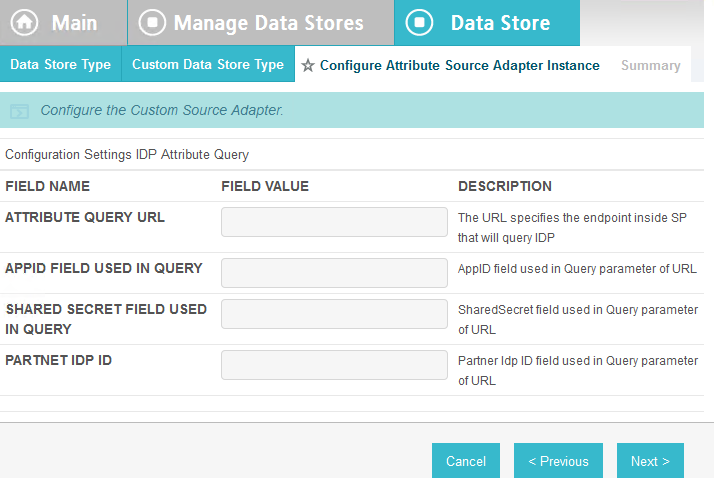
10.4. NextLabs PIP Plugin
10.4.1. Architecture
The NextLabs Control Center can support custom PIP plugin extensions for dynamic user and resource attribute retrieval during runtime. In order to install and deploy a PIP plugin such as the one described in this section, it is necessary to have previously installed and deployed the NextLabs Control Center, Policy Controller, Policy Studio, and the NextLabs Entitlement Manager (Section 7).
According to the NextLabs PDP Policy Extension documentation, which is only available to NextLabs customers at this time, one method for leveraging this PIP extension capability is by way of a getAttribute() function within a UserAttrProviderMod class. The PIP Plugin implements methods defined by the ISubjectAttributeProvider interface. The ISubjectAttributeProvider interface declares the method getAttribute() function which enables querying for a single subject attribute sequentially until all missing required attributes have been requested.
10.4.1.1. Required classes of the NextLabs PIP Plugin:
UserAttrProviderMod class must exist and must contain a getAttribute() function.
- The getAttribute() function must accept two arguments (IDSubject and String) and return an EvalValue. The EvalValue is created using its build() function and the attribute value ultimately returned from the Protocol Broker (see Section 10.5).
HTTPSTransmitter class
- makes an HTTPS request to the Protocol Broker using a doPost() function
CacheKey class, implementing a local Ehcache
- The CacheKey class constructor takes two parameters, the subjectId and the attributeName, which serve as a compound cache key for storing and retrieving the value of a given user’s attribute within the plugin’s local Ehcache.
10.4.1.2. Other Required Files or Deployment Notes:
The three above classes must be compiled into a .jar file.
Our method of compilation in this build was using Apache Maven 3.2.5. Maven compilations are directed by a pom.xml (“Project Object Model”), which is an XML representation of a Maven project. More information about Apache Maven and its pom file requirements can be found here: https://maven.apache.org/pom.html
According to NextLabs support, be sure to include within the pom.xml file configuration a statement that specifies the Provider-Class. The Provider-Class is the UserAttrProviderMod class that contains the getAttribute() method. Example pom.xml excerpt from the pom.xml file in this implementation:
<configuration>
    <archive>
        <manifest>
            <mainClass>nist.pdpplugin.UserAttrProviderMod</mainClass>
        </manifest>
        <manifestEntries>
            <Provider-Class>nist.pdpplugin.UserAttrProviderMod</Provider-Class>
        </manifestEntries>
    </archive>
</configuration>
Also required per NextLabs support documentation, for any custom plugin you must include a properties file.
The configuration file should end with the “.properties” file extension. Example from this implementation: nlsamlpluginService.properties
Contents should be similar to our example copied below. You must include a category = ADVANCED CONDITION statement per NextLabs deployment and loading requirements:
name = NLSAMLPlugin_Service
jar-path = [NextLabs]/Policy Controller/jservice/jar/nlsamlplugin/NLSAMLPlugin-0.0.1-SNAPSHOT-jar-with-dependencies.jar
friendly_name = NLSAMLPlugin Service
description = NLSAMLPlugin Service
10.4.1.3. Notes on Jar and Properties File Deployment within NextLabs Policy Controller Software Architecture:
The jar file containing the three classes must be deployed on the SharePoint server within the NextLabs Policy Controller software architecture in a specific location. Under the C:/Program Files/NextLabs/Policy Controller/jservice/jar folder you must create a folder specifically for your custom jar, i.e., C:/Program Files/NextLabs/Policy Controller/jservice/jar/custom_jar_folder_you_create
Any other required supporting jars can be compiled within the same jar as the UserAttrProviderMod class and other classes deployed as described in the previous step.
- Otherwise, any additional required supporting jars can be compiled into a separate jar which is deployed elsewhere within the NextLabs Policy Controller software architecture on the SharePoint server, i.e., C:/Program Files/NextLabs/Policy Controller/jre/lib/ext/
The properties file must be deployed on the SharePoint server within the NextLabs Policy Controller software architecture in a specific location, under the C:/Program Files/NextLabs/Policy Controller/jservice/config folder, i.e., C:/Program Files/NextLabs/Policy Controller/jservice/config/jarpropertiesfile.properties
10.4.2. Understanding How the NextLabs PIP Plugin Interacts with Build Components
When a policy is executed and the NextLabs Policy Controller PDP determines that attributes sent in the initial set up of the session are insufficient, the getAttribute() function in the UserAttrProviderMod within the NextLabs Plugin jar is automatically executed sequentially for each missing attribute.
As described above, when the initial set of attributes is insufficient, the NextLabs PIP Plugin first checks a local cache, implemented using the Ehcache library and a CacheKey class illustrated above. If the requested attribute exists within the local cache, the NextLabs PIP Plugin retrieves and returns it immediately for use during policy evaluation by the Policy Controller (PDP).
If the requested attribute does not exist within the local cache, the NextLabs PIP Plugin’s HTTPSTransmitter class makes an https request to the Protocol Broker using a doPost() function. The Protocol Broker performs its functions and returns either the desired attribute or an exception back to the NextLabs PIP Plugin, where the Policy Controller (PDP) can evaluate the relevant ABAC policy and determine an access decision. In the case that the requested attribute does not exist, the NextLabs Policy Controller PDP is configured to default to Deny access in our build. The NextLabs Policy Controller PDP is also configured to Deny Access whenever the Protocol Broker or the NextLabs PIP Plugin produces an exception.
Figure 10‑4 NextLabs PIP Plugin Class Diagram
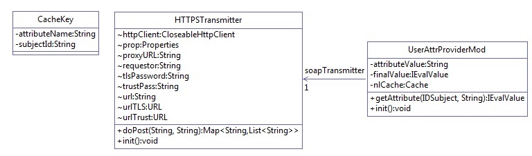
Figure 10‑5 NextLabs PIP Plugin Interaction Diagram
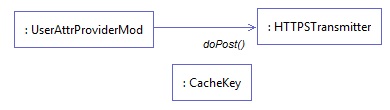
10.4.3. Compilation and Deployment
10.4.3.1. Compiling the NextLabs PIP Plugin Jar
- Verify that you are on the server hosting your SharePoint instance, called the SharePoint server in our build.
- Click on the Windows icon and begin typing Cmd.
- Double-click the icon to open the Command Prompt.
- In the Command Prompt window, navigate to the folder where your pom.xml exists and click Enter, i.e., cd C:/software/java/plugin/
- In the Command Prompt window, run the following command and press Enter to compile your files and jar(s) into a single jar: mvn clean install
10.4.3.2. Stopping the NextLabs Policy Controller Service Before NextLabs PIP Plugin Jar Deployment
Still on the SharePoint server, click on the Windows icon and begin typing Services.
Double-click the icon to open the Services application.
In the Services application window, in the list of services, click on the Name column to sort by alphabetical order and look for Control Center Enforcer Service.
If the status of the Control Center Enforcer Service is running, stop it by following these steps:
Click on the Windows icon.
On your main screen, double-click the Stop Policy Controller shortcut.
Enter your NextLabs Administrator credentials, then click Stop.
Click OK.
10.4.3.3. Deploying the NextLabs PIP Plugin Jar and its Configuration File
- Still on the SharePoint server, Click on the Windows icon and begin typing Cmd.
- Double-click the icon to open the Command Prompt.
- In the Command Prompt window, navigate to the folder where your NextLabs Policy Controller installation exists, and into its /jservices/jar folder where custom plugins are required to be stored, then press Enter. i.e., cd C:/Program Files/NextLabs/Policy Controller/jservice/jar/
- In the Command Prompt window, enter a command similar to the following and press Enter to create an empty folder named after your plugin: mkdir nlsamlplugin
- In the Command Prompt window, enter a command similar to the following and press Enter to copy your plugin jar from its existing location (example C:/software/java/plugin/target/) to the new plugin folder you just created: copy “C:/software/java/plugin/target/plugin.jar” “nlsamlplugin/”
- In the Command Prompt window, enter a command to navigate to the folder where your NextLabs Policy Controller installation exists, and into its jservices folder which contains the config folder where custom plugin .properties files are required to be stored, then press Enter. i.e., cd C:/Program Files/NextLabs/Policy Controller/jservice/
- In the Command Prompt window, enter a command similar to the following and press Enter to copy your plugin .properties file from its existing location (example C:/software/java/plugin/) to the config folder: copy “C:/software/java/plugin/nlsamlpluginService.properties” “config/”
10.4.3.4. Resetting IIS and Restarting the NextLabs Policy Controller Service
Click on the Windows icon and begin typing PowerShell.
Double-click the icon to open Windows PowerShell.
In the Windows PowerShell window, type in this command and press Enter to reset Internet Information Services: iisreset
Click on the Windows icon and begin typing Services.
Double-click the icon to open the Services application.
Within the Services application window, in the list of services, click on the Name column to sort by alphabetical order and look for Control Center Enforcer Service.
Right-click Control Center Enforcer Service and click Start.
It may be necessary to click the Refresh icon in order to see the Control Center Enforcer Service status change to running.
10.5. Protocol Broker
10.5.1. Architecture
The Protocol Broker decouples communication between the NextLabs Plugin and PingFederate RP. As noted earlier, the Protocol Broker is a web application hosted on a tomcat server installed on the SharePoint server. It communicates using mutual TLS and listens on the localhost. This ensures that the service provided by Protocol Broker is not available on the network, and the requester must be authenticated during each request.
SAMLProxy extends the HttpServlet class, which is an abstract class. This enables SAMLProxy class to read/write the http request/response, and determines the http method of the request (i.e. HTTP GET, POST, PUT, DELETE, HEAD etc) and calls one of the corresponding methods. The SAMLProxy class only implements the POST method.
The SAMLProxy class constructs an object of the SoapHTTPTransmitter class. This class reads abacClient.jks and truststore.jks which are used for mutual TLS communication initiated by the SoapHTTPTransmitter with PingFederate. It also reads abacSigningClient.jks, which is used to sign the SAML AttributeQuery, and metadata to verify the SAML Response signature. The jks extension stands for Java Key store, which is a storage facility for cryptographic keys and certificates.
The Protocol Broker facilitates secure communication between the NextLabs PIP Plugin and PingFederate RP. This coordination consists of two parts:
- Communication between the NextLabs PIP Plugin and the Protocol Broker
- Communication between the Protocol Broker and the PingFederate RP server
10.5.1.1. Communication Between NextLabs PIP Plugin and Protocol Broker
The Protocol Broker’s doPost() method expects the following parameters:
- Requester
- SubjectId
- AttributeName
On successful receipt of a request, SAMLProxy uses the SoapHTTPTransmitter class to transmit the request to the PingFederate RP server. The response received from SOAPHTTPTransmitter is dispatched back to the NextLabs PIP Plugin, which then hands the result off to the PDP for policy evaluation and access decision making.
10.5.1.2. Communication Between Protocol Broker and PingFederate RP Server
The PingFederateRP and ProtocolBroker communicate using Assertion Query/Request Profile. As shown in Figure 10‑6, Protocol Broker initiates the secured communication on a mutual TLS channel with the Relying Party, and sends a signed SAML2 AttributeQuery. The message format and structure of the AttributeQuery is defined by SAMLCore Section 3.3.2.3. Binding for the profile is defined by SAMLBind Section 3.2.3. Processing rules governing the profile are provided by Section 3.3 of SAMLCore. In response, Protocol Broker expects a SAML response back.
OpenSAML is used to implement an Assertion Query/Request Profile. OpenSAML is a set of open source libraries meant to support developers working with Security Assertion Markup Language (SAML). The configuration required to use the OpenSAML library is provided in Section 10.5.2.2.
Figure 10‑6 Communication Between Plugin and Relying Party

Based on keystores and configuration read during initialization, SoapHTTPTransmitter creates a SAML2AttributeQuerBuilder class to build a Signed SAML 2.0 Attribute Query. Attribute names received earlier in the doPost() method are used to build the AttributeQuery. A SOAPSAML2 object is used to provide SOAP parameters for the SAML message created earlier. It reads SAML 2.0 metadata to find the location of the Attribute Authority end point. It uses HttpSOAPClient to dispatch the request to the end point using mutual TLS.
HTTPSoapClient is also responsible for receiving the Attribute response, verifying the signature and sending the attributes back to the Nextlab Plugin.
Figure 10‑7 Protocol Broker Interaction Diagram

Figure 10‑8 Protocol Broker Class Diagram
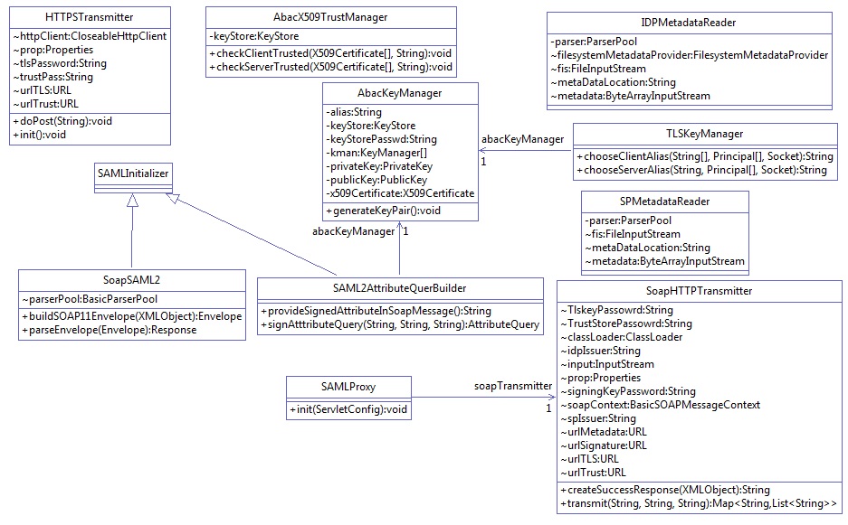
10.5.2. Deployment
10.5.2.1. System and Environment Requirements
The Protocol Broker is deployed on tomcat 8.0.22 on the SharePoint server, and uses OpenSAML 2.6.4.
10.5.2.2. Configuration
In order to accept traffic only on the channel protected by mutual TLS:
Install tomcat on the SharePoint server. The tomcat installation procedure is provided here.
Open the configuration file server.xml inside the configuration directory of the tomcat installation. Comment out the section:
<!--
    <Connector port="8080" protocol="HTTP/1.1"
     connectionTimeout="20000"
     redirectPort="8443" />
 -->
Update/insert the following line:
<Connector
    port="8443"
    protocol="org.apache.coyote.http11.Http11NioProtocol"
    maxThreads="150"
    SSLEnabled="true"
    scheme="https"
    secure="true"
    keystoreFile="C:\Users\<name>\Documents\softwares\tomcat\apache-tomcat-8.0.22\conf\abacTomcat.jks"
    keystorePass="…..password"
    clientAuth="true"
    sslProtocol="TLS"
    truststoreFile="C:\Users\sjha\Documents\softwares\tomcat\apache-tomcat-8.0.22\conf\truststore.jks"
    truststoreType="JKS"
    truststorePass="…password"/>
The configuration details for OpenSAML are provided here. In this demonstration, a folder called endorsed is created inside the lib directory of tomcat installation.
Add the following libraries to the endorsed folder created in the above step:
- xml-apis-2.10.0.jar
- xml-resolver-1.2.jar
- xercesImpl-2.10.0.jar
- xalan-2.7.1.jar
- serializer-2.10.0.jar
10.5.2.3. Preparation and Compilation
In our build, we used Apache Maven for Protocol Broker compilation. In order to prepare and compile the Protocol Broker, follow these steps:
10.5.2.3.1. Preparation
On the SharePoint server, click on the Windows icon and begin typing Cmd.
Double-click the icon to open the Command Prompt.
In the Command Prompt window, navigate to the folder where your pom.xml for the Protocol Broker exists, and press Enter. i.e., cd C:/software/java/samlNewPlugin/
Type the following command, then press Enter to prepare for compilation of the new Protocol Broker: .war file: mvn clean
Verify that your results are similar to the following, including the Build Success statement:
[INFO] Scanning for projects...
[INFO]
[INFO] ------------------------------------------------------------------------
[INFO] Building SAMLProxy 0.0.1-SNAPSHOT
[INFO] ------------------------------------------------------------------------
[INFO]
[INFO] --- maven-clean-plugin:2.5:clean (default-clean) @ SAMLProxy ---
[INFO] Deleting /home/sjha/pdpPlugins/SAMLProxy/target
[INFO] ------------------------------------------------------------------------
[INFO] BUILD SUCCESS
[INFO] ------------------------------------------------------------------------
[INFO] Total time: 1.333 s
[INFO] Finished at: 2015-06-29T10:24:27-04:00
[INFO] Final Memory: 5M/15M
[INFO] ------------------------------------------------------------------------
10.5.2.3.2. Compiling the .war File
After following the instructions above to prepare for compiling, within the Command Prompt window, enter the following command and press Enter to create the Protocol Broker: .war file: mvn package
Verify that your results are similar to the following, including the Failures: 0 and Build Success portions:
[INFO] Scanning for projects...
[INFO]
[INFO] ------------------------------------------------------------------------
[INFO] Building SAMLProxy 0.0.1-SNAPSHOT
[INFO] ------------------------------------------------------------------------
[INFO]
[INFO] --- maven-resources-plugin:2.6:resources (default-resources) @ SAMLProxy ---
[INFO] Using 'UTF-8' encoding to copy filtered resources.
[INFO] Copying 9 resources
[INFO]
[INFO] --- maven-compiler-plugin:3.1:compile (default-compile) @ SAMLProxy ---
[INFO] Nothing to compile - all classes are up to date
[INFO]
[INFO] --- maven-resources-plugin:2.6:testResources (default-testResources) @ SAMLProxy ---
[INFO] Using 'UTF-8' encoding to copy filtered resources.
[INFO] skip non existing resourceDirectory /home/sjha/pdpPlugins/SAMLProxy/src/test/resources
[INFO]
[INFO] --- maven-compiler-plugin:3.1:testCompile (default-testCompile) @ SAMLProxy ---
[INFO] Nothing to compile - all classes are up to date
[INFO]
[INFO] --- maven-surefire-plugin:2.12.4:test (default-test) @ SAMLProxy ---
[INFO] Surefire report directory: /home/sjha/pdpPlugins/SAMLProxy/target/surefire-reports

-------------------------------------------------------
 T E S T S
-------------------------------------------------------
Running nist.pdpplugin.AppTest
Tests run: 1, Failures: 0, Errors: 0, Skipped: 0, Time elapsed: 0.03 sec

Results :

Tests run: 1, Failures: 0, Errors: 0, Skipped: 0

[INFO]
[INFO] --- maven-war-plugin:2.6:war (default-war) @ SAMLProxy ---
[INFO] Packaging webapp
[INFO] Assembling webapp [SAMLProxy] in [/home/sjha/pdpPlugins/SAMLProxy/target/SAMLProxy-0.0.1-SNAPSHOT]
[INFO] Processing war project
[INFO] Copying webapp resources [/home/sjha/pdpPlugins/SAMLProxy/WebContent]
[INFO] Webapp assembled in [440 msecs]
[INFO] Building war: /home/sjha/pdpPlugins/SAMLProxy/target/SAMLProxy-0.0.1-SNAPSHOT.war
[INFO] ------------------------------------------------------------------------
[INFO] BUILD SUCCESS
[INFO] ------------------------------------------------------------------------
[INFO] Total time: 6.281 s
[INFO] Finished at: 2015-06-29T10:27:14-04:00
[INFO] Final Memory: 11M/26M
[INFO] ------------------------------------------------------------------------
10.5.3. Example SAML Request and Response Output
10.5.3.1. Example of Tomcat Output from our Build that Illustrates a SAML Request
<saml2p:AttributeQuery ID="_7a41be2e3d0d1abea13e857a80b3cfbc" IssueInstant="2015-05-26T18:14:39.405Z" Version="2.0" xmlns:saml2p="urn:oasis:names:tc:SAML:2.0:protocol" xmlns:soap11="http://schemas.xmlsoap.org/soap/envelope/">
<saml2:Issuer xmlns:saml2="urn:oasis:names:tc:SAML:2.0:assertion">urn:nccoe:abac:plugin</saml2:Issuer>
<ds:Signature xmlns:ds="http://www.w3.org/2000/09/xmldsig#">
    <ds:SignedInfo>
        <ds:CanonicalizationMethod Algorithm="http://www.w3.org/2001/10/xml-exc-c14n#"/>
        <ds:SignatureMethod Algorithm="http://www.w3.org/2000/09/xmldsig#rsa-sha1"/>
        <ds:Reference URI="#_7a41be2e3d0d1abea13e857a80b3cfbc">
            <ds:Transforms>
                <ds:Transform Algorithm="http://www.w3.org/2000/09/xmldsig#enveloped-signature"/>
                <ds:Transform Algorithm="http://www.w3.org/2001/10/xml-exc-c14n#"/>
            </ds:Transforms>
            <ds:DigestMethod Algorithm="http://www.w3.org/2000/09/xmldsig#sha1"/>
            <ds:DigestValue>hz3JxkkIsCL/BVlkRCrgUykjbho=</ds:DigestValue>
        </ds:Reference>
    </ds:SignedInfo>
    <ds:SignatureValue>O8Gc8CSVKeYoNsR8bWaiExEpumeO2bLaMwlWC6LNaqf9ydvMPw/gcZbAEATCgK/RXVYgTe7ikYKKC80/GiO7NrUKZPO86ln5LINX5Gw5iTOeb6S4zUTWEfp2PQTfMSTB6rZe5OBuUDEpWfJ4T/3E1KpI4H7sxoaYhcZ3J2i1ZxPheMEJ0l4zvicAzlsefiirftn1vWirOdjub9VE0SicCl11FJB13Wla+c8JA5Nbbsnc3H6h5oDeapEOD9bX41KZtj2sGbh6k+F3vunYpd3m69KW6z8CJQeBWOcGCmDtt4Dyf/avG6Iz7o0PYjPYxFIvwslOYYU2QzLtOpHT8e/RRQ==</ds:SignatureValue>
    <ds:KeyInfo>
        <ds:KeyValue>
            <ds:RSAKeyValue>
                <ds:Modulus>uzxrL5iAIpNyEXHmGTDW1mzx7YJal/c9Ruxag3sifjzuUdBjEznFJJxaagM2pzTUI5JCaLzgm71V SBmuVL+6PzTxReM3i5XzWjpgRMIizadnQT0wmCryKuNaQiBIFLoMbi+ySdBvu+M/xhHlRxuFjY9N PSE1MHL8YaLoKW2SFIm/3bhJ/xF7q7FGHMcJH4Zzr2QpQmBEryozJJV3z4ZvVro/MfyLg1VER0pu
                    36e32hIyzsf2gKizv00qY2ecDlBCNTITsA2HWSTf50kpvT4qupCnXVKVqzDPZON0XCsJJcwWsUi9 pRvkGtVBXqhh282ODyzcl3nkpgsl5F8hR7kOjQ==</ds:Modulus>
                <ds:Exponent>AQAB</ds:Exponent>
            </ds:RSAKeyValue>
        </ds:KeyValue>
    </ds:KeyInfo>
</ds:Signature>
<saml2:Subject xmlns:saml2="urn:oasis:names:tc:SAML:2.0:assertion">
    <saml2:NameID Format="urn:oasis:names:tc:SAML:1.1:nameid-format:unspecified">jdoe</saml2:NameID>
</saml2:Subject>
<saml2:Attribute Name="firstname" NameFormat="urn:oasis:names:tc:SAML:2.0:attrname-format:basic" xmlns:saml2="urn:oasis:names:tc:SAML:2.0:assertion"/>
</saml2p:AttributeQuery>
10.5.3.2. Example of Tomcat Output from our Build that Illustrates a SAML Response
<?xml version="1.0" encoding="UTF-8"?>
<S11:Envelope xmlns:S11="http://schemas.xmlsoap.org/soap/envelo
  pe/">
    <S11:Body>
        <samlp:Response xmlns:samlp="urn:oasis:names:tc:SAML:2.0:protocol" ID="LkF9NevJONpgbE56hszqbo2V
      FZH" InResponseTo="_13caab0c0aa8b70946be278ff32376ad" IssueInstant="2015-06-29T14:46:35.617Z" Version="2.0">
            <saml:Issuer xmlns:saml="urn:oasis:names:tc:SAML:2.0:assertion">https://rp.abac.test:9031</saml:Issuer>
            <samlp:Status>
                <samlp:StatusCode Value="urn:oasis:names:tc:SAML:2.0:status:Success"/>
            </samlp:Status>
            <saml:Assertion xmlns:saml="urn:oasis:names:tc:SAML:2.0:assertion" ID="P-nmuwJENgb_aVjhd5DpY
          dfN2IU" IssueInstant="2015-06-29T14:46:35.945Z" Version="2.0">
                <saml:Issuer>https://rp.abac.test:9031</saml:Issuer>
                <saml2:Subject xmlns:saml2="urn:oasis:names:tc:SAML:2.0:assertion" xmlns:saml2p="urn:oasi
            s:names:tc:SAML:2.0:protocol" xmlns:soap11="http://schemas.xmlsoap.org/soap/envelope/">
                    <saml2:NameID Format="urn:oasis:names:tc:SAML:1.1:nameid-format:unspecified">lsmith@ab ac.test</saml2:NameID>
                </saml2:Subject>
                <saml:Conditions NotBefore="2015-06-29T14:41:35.945Z" NotOnOrAfter="2015-06-29T14:51:35.9
            45Z">
                    <saml:AudienceRestriction>
                        <saml:Audience>https://nextlabs-rp</saml:Audience>
                    </saml:AudienceRestriction>
                </saml:Conditions>
                <saml:AttributeStatement>
                    <saml:Attribute Name="stafflevel" NameFormat="urn:oasis:names:tc:SAML:2.0:attrname-for
              mat:basic">
                        <saml:AttributeValue xmlns:xs="http://www.w3.org/2001/XMLSchema" xmlns:xsi="http://
                www.w3.org/2001/XMLSchema-instance" xsi:type="xs:string">Junior</saml:AttributeValue>
                    </saml:Attribute>
                </saml:AttributeStatement>
            </saml:Assertion>
        </samlp:Response>
    </S11:Body>
</S11:Envelope>
10.6. Apache Directory Service (ApacheDS)
ApacheDS is included in Apache Directory Studio, which has multiple functionalities with ApacheDS Server, i.e., LDAP Browser, Schema Editor, Apache Configurator, LDIF Editor, Embedded ApacheDS, and ACI Editor.
10.6.1. Layout
Before installation, it is important to consider system needs and match them with the installation layout. The general layout for ApacheDS consists of two major concepts:
- Installation Layout: The installation is where all files essential to ApacheDS are stored, i.e., launch script, libraries, and a service wrapper (depending on the kind of installer used).
- Instance Layout: ApacheDS is built to run multiple instances of the server at the same time, which means that an optional instances folder can be found in the installation layout (or elsewhere on the disk, depending on the platform). In that folder you will find one or multiple directories, all sharing the same layout, corresponding to all ApacheDS instances (one directory per instance, with names corresponding to the ID of the instance).
A detailed discussion of these concepts can be found here.
10.6.2. Download
ApacheDS can be downloaded as binary or as source, and compiled on a given platform. Source can be downloaded here.
In this project, ApacheDS was downloaded as a packaged Windows installer from this location. Native installers are available in the following formats, and their download links are available at following site.
| Platform | Installer Format |
|---|---|
| Window | Exe |
| Mac OS X | Dmg |
| Debian | Deb |
| Linux | Rpm,bin |
- At the download location, you will see a URL as shown in the example below. Click the link above to download Apache Directory Server for Windows.
Figure 10‑9 ApacheDS Download
During the software download, different installation graphics will be displayed depending on which browser you use. Example from Windows Internet Explorer:

On Chrome, it may display as below (if you are not using command line tools):

10.6.2.1. Verify the Integrity of the Downloaded File
It is essential to verify the integrity of the file when the download completes.
The file’s integrity can be verified with PGP signatures using PGP or GPG. First, download the KEYS and the *asc* signature file for the relevant distribution. Both KEYS and asc can be found to the right of the download link, as shown in Figure 10‑9 above.
Verify the signatures using the following commands in the Command Prompt:
$ pgpk -a KEYS
$ pgpv apacheds-2.0.0-M20.exe.asc
or
$ pgp -ka KEYS
$ pgp apacheds-2.0.0-M20.exe.asc
or
$ gpg --import KEYS
$ gpg --verify apacheds-2.0.0-M20.exe.asc
Alternatively, you can verify the MD5 signature on the files. A Unix program called md5 or md5sum is included in many Unix distributions. It is also available as part of GNU Textutils. Windows users can get binary md5 programs from here, here, or here.
10.6.3. Installation
Note: To install ApacheDS as a Windows service, you need administrative privileges. We installed ApacheDS on Windows Server 2012. The ApacheDS installation procedure for other operating systems can be found here.
Once ApacheDS is downloaded and verified, double-click the installer to open it. Note: It may have already been opened by your web browser.
When the following screen appears, click Next.
Review the License agreement and click I Agree.
The next screen prompts you for the install path. In our build, we left the default install path. Specify an install path of your choosing, and click Next.
Specify a location for storing ApacheDS instances, then click Next.
The next screen asks for the location of your java run time. It is assumed, based on the earlier description in Section 10.8.2, that users will have the proper java environment prior to attempting to install ApacheDS. Users who have no JRE installed should abandon the install by clicking Cancel. Install the JRE and re-run the ApacheDS install. We accepted the default as shown.

Click Install. Once the installation is complete, you will receive the following prompt:
10.6.3.1. Functional Test of the ApacheDS Installation
Click Show Details in above diagram to see details of installation. Make sure all of the folders exist, then click Next.
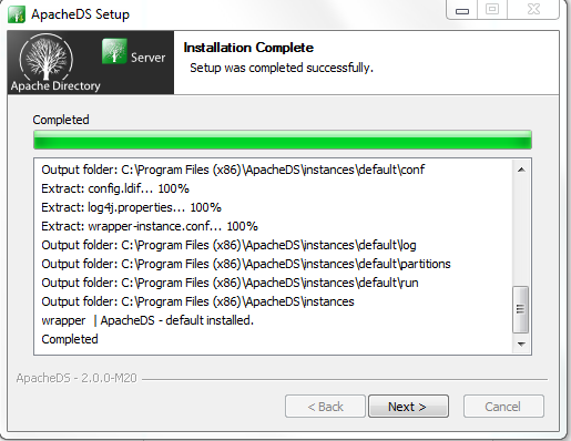
Click Finish to end the installation.
Click Yes to start the ApacheDS server. Instructions are provided in Section 10.6.2.
10.6.4. Starting and Stopping the Server
The server can be started and stopped with the Windows Services manager (Control Panel > Administrative Tools > Services). The user must have administrative privileges.
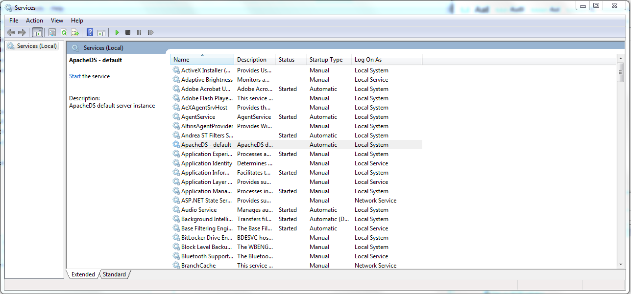
From here, ApacheDS can be started, stopped, or restarted.
The process for starting and stopping ApacheDS on other operating systems is described here.
10.7. PingFederate - Apache Integration
This section requires knowledge of the following pieces of information:
- Server IP address or hostname
- Server port where it is listening on
- Server credentials (i.e., private key and certificate) to be provisioned on directory server
10.7.1. Provisioning of Server Credential
Start Apache Directory Server Studio and open a new connection.
10.7.1.1. Creation of Server Connection
To create a new LDAPS connection, complete the following steps:
Define network parameters.
Define authentication parameters.
Define additional browser options (optional).
Define additional edit options (optional).
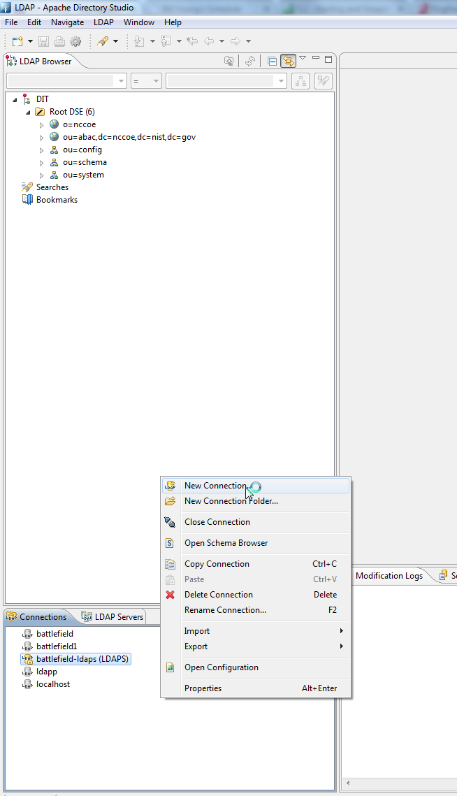
Once a new connection is opened, the following screen appears. Fill in Hostname and Port. Select the encryption method Use SSL encryption(ldaps://), then click Next.
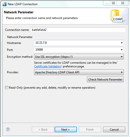
| Option | Description | Default |
|---|---|---|
| Connection name | The name of the connection. In the Connections view, the connection is listed with this name. The name must be unique. | empty |
| Hostname | The hostname or IP address of the LDAP server. A history of recently used hostnames is available through the drop-down list. | empty |
| Port | The port of the LDAP server. The default port for non-encyrpted connections is 389. The default port for ldaps:// connections is 636. A history of recently used ports is available through the drop-down list. | 10636 |
| Encryption method | The encryption to use. Possible values are: No encryption, ldaps:// and StartTLS extension. | No encryption |
| Provider | Option to choose either JNDI or Apache Directory LDAP client API | |
| Check network parameter | Use this function if you want validate that the entered information is correct, and the server is reachable. | |
| Read-Only | If this option is chosen, any attempts to modify will return an error. |
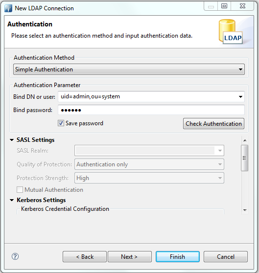
| Option | Description | Default |
|---|---|---|
| Authentication Method | Select your authentication method:
|
Simple Authentication |
| Bind DN or user | The distinguished name or user ID used to bind. Previously entered DNs can be selected from drop-down list. | empty |
| Bind Password | The password used to bind. | empty |
| Save password | If checked, the password will be saved in configuration. If not checked, you must enter the password whenever you connect to the server. Warning: The password is saved as plain text. | checked |
| Check Authentication | Use this function to attempt a connection plus a bind to the host upon completion of the wizard. It will validate that the entered information is correct. |
This project does not use SASL or Kerberos.
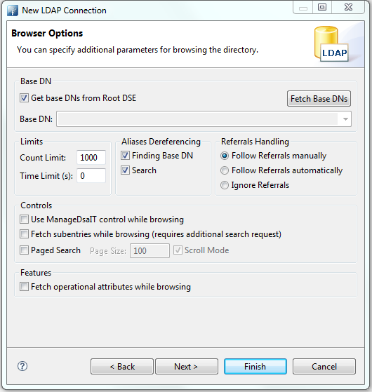
| Option | Description | Default |
|---|---|---|
| Get base DNs from Root DSE | If checked, the base DNs are fetched from the namingContexts attribute of the Root DSE. | checked |
| Fetch Base DNs | Use this function to get the namingContext values from the Root DSE. The returned values will appear in the Base DN drop-down list. | |
| Base DN | The Base DN to use. You may enter a DN manually or select one from the drop-down list. This field is only enabled if the option Get base DNs from root DSE is off. | empty |
| Count Limit | Maximum number of entries returned from the server when browsing the directory. It is also used as default value when searching the directory. A value of 0 means no count limit. Note that this value is a client-side value. It is also possible to use a server-side limit. | 1000 |
| Time Limit | The maximum time in seconds the server searches for results. This is used as default value when browsing or searching the directory. A value of 0 means no limit. Note that this value is a client-side value. It is also possible to use a server-side limit. | 0 |
| Alias Dereferencing | Specifies whether aliases should be dereferenced while finding the search base entry, when performing the search, or both. To manage (create, modify, delete) alias objects you must uncheck both options. | Both finding and searching |
| Referrals Handling | Specifies the referral handling.
|
Follow Referrals manually |
| Use ManageDsaIT control while browsing | If enabled, the ManageDsaIT control is sent to the server in each request. This signals the directory server not to send referrals and search continuations, but return the special referral objects. Note: This is only applicable if the directory server supports the ManageDsaIT control. | unchecked |
| Fetch subentries while browsing | If enabled, both normal and subentries according to RFC 3672 are fetched. This causes additional search requests while browsing the directory. | unchecked |
| Paged Search | If enabled, the simple paged result control is used while browsing the directory. With page size you can define how many entries should be retrieved in one request. If Scroll Mode is enabled, only one page is fetched from the server at a time. While browsing, you can scroll through the pages by using next page and top page. If disabled, all entries are fetched from the server. The paged result control is only used in the background to avoid server-side limits. | unchecked |
| Fetch operational attributes while browsing | If enabled, both user attributes and operational attributes are retrieved while browsing. If the server supports the feature All Operational Attributes, use + to retrieve operational attributes. Otherwise, all operational attributes defined in the schema are requested. | unchecked |

| Option | Description | Default |
|---|---|---|
| Modify Mode | Specify the modify mode for attributes with an equality matching rule. Options:
|
Optimized Modify Operations |
| Modify Mode (no equality matching rule) | Specify the modify mode for attributes with no equality matching rule. Options:
Recommended values for various LDAP servers:
|
Optimized Modify Operations |
| Modify Order | Specify the modify order when using add and delete operations. | Delete first |
Go to Open Configuration for the newly created connection.
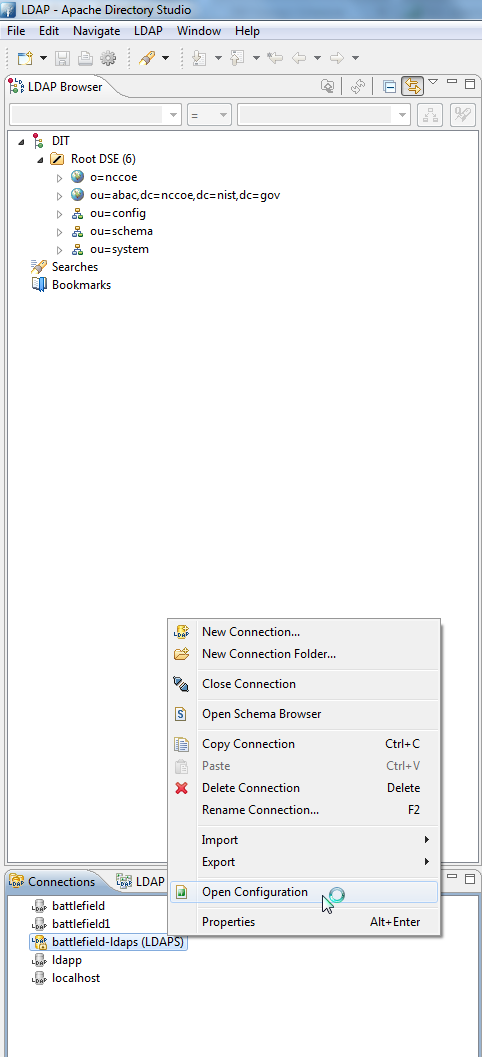
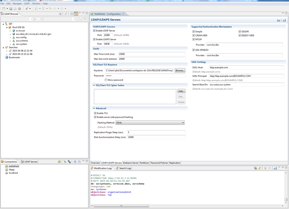
| Property | Default Value | Description |
|---|---|---|
| keystoreFile | none | Path of the X509 (or JKS) certificate file for LDAPS |
| certificatePassword | changeit | Password used to load the LDAPS certificate file |
| port | 10636 | LDAPS TCP/IP port number to listen to |
| enableSSL | true | Sets if SSL is enabled or not |
- Make sure Enable LDAPS Server is checked, and Port is the same as provided during creation of the connection.
- Go to SSL/Start TLS Keystore.
- Provide the location of the Keystore file and the password for the certificate.
- Save the configuration.
- Restart the server.
10.7.1.2. Verification
OpenSSL was used to acquire the server public certificate.
>openssl s_client -showcerts -connect 10.33.7.8:10636 < /dev/null | openssl x509 -outform PEM > dir.pem
depth=0 C = US, O = ASF, OU = Directory, CN = battlefield.bb-abac-bb1.nccoe.lab
verify error:num=20:unable to get local issuer certificate
verify return:1
depth=0 C = US, O = ASF, OU = Directory, CN = battlefield.bb-abac-bb1.nccoe.lab
verify error:num=27:certificate not trusted
verify return:1
depth=0 C = US, O = ASF, OU = Directory, CN = battlefield.bb-abac-bb1.nccoe.lab
verify error:num=21:unable to verify the first certificate
verify return:1
DONE
[sjha@battlefield ~]$ more dir.pem
-----BEGIN CERTIFICATE-----
MIIBjDCCATYCBgFMlJE24DANBgkqhkiG9w0BAQUFADBCMQswCQYDVQQGEwJVUzEM
MAoGA1UEChMDQVNGMRIwEAYDVQQLEwlEaXJlY3RvcnkxETAPBgNVBAMTCEFwYWNo
ZURTMB4XDTE1MDQwNzE1NDgwN1oXDTE2MDQwNjE1NDgwN1owWzELMAkGA1UEBhMC
VVMxDDAKBgNVBAoTA0FTRjESMBAGA1UECxMJRGlyZWN0b3J5MSowKAYDVQQDEyFi
YXR0bGVmaWVsZC5iYi1hYmFjLWJiMS5uY2NvZS5sYWIwXDANBgkqhkiG9w0BAQEF
AANLADBIAkEAlLYJY8PJgMS82IqrW4uTVobkNqi2oJBoFAvOGMF7olPCQ4x5vrgS
6GEq9gUHk1ZZzymIIq6BMxoEb80l6lPY/wIDAQABMA0GCSqGSIb3DQEBBQUAA0EA
hXNpaGfF2Aboemwzt6U/fvSNyl+KRdeKFm0liWbseBk8OPvdOEmW96HVLvlbxSlc
JpSznkLFhFOe0fimwB6GEg==
-----END CERTIFICATE-----
- Verify the certificate received from the directory server against the certificate that was loaded earlier.
10.7.1.3. Configuration Steps on PingFederate RP Server
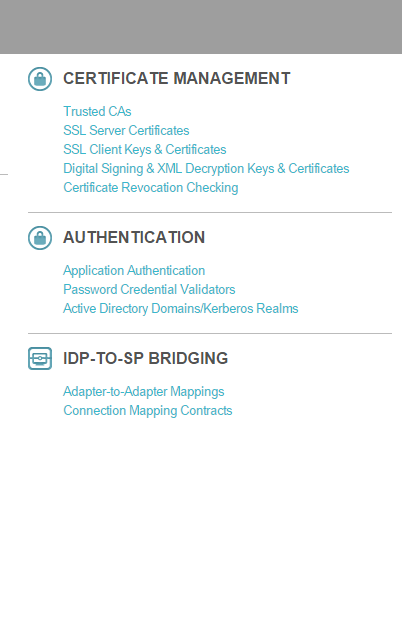
The following screen will appear, displaying all certificates on the server’s global trust list.
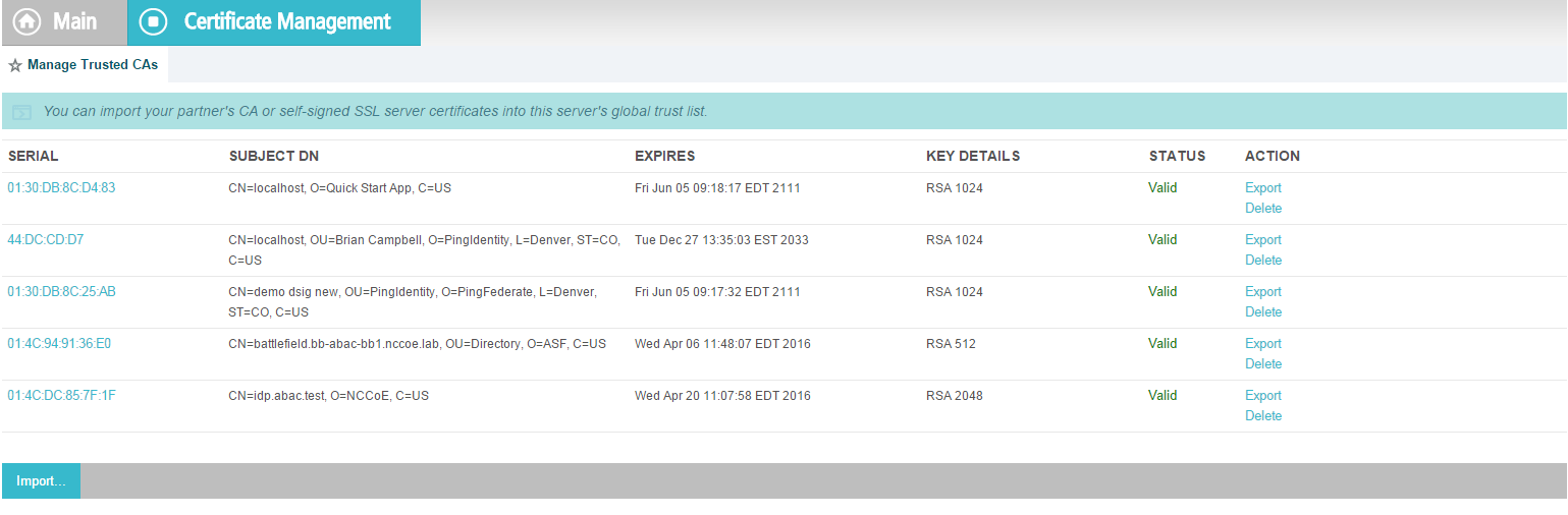
Select Import Certificate.
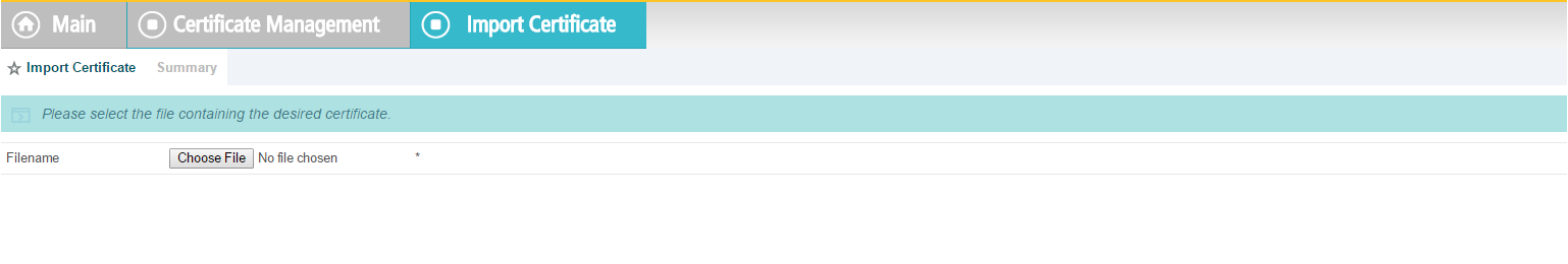
Choose a file to import.
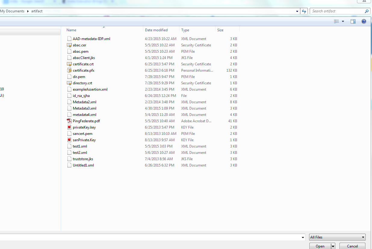
Once your chosen file appears in the Filename field, click Next.
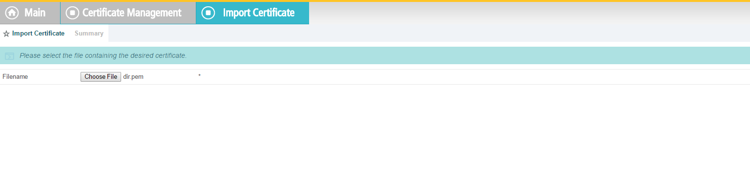
View the Summary of the imported certificate.
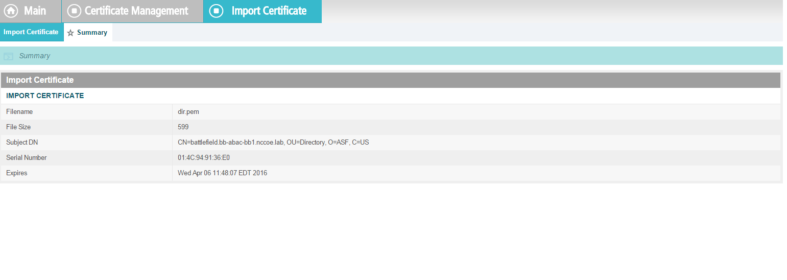
Click Done. The main screen will display a list of certificates. Click Save.
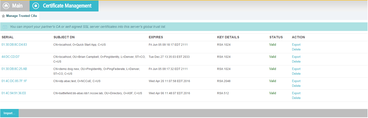
10.7.1.3.1. Creation of Data Store to Connect to ApacheDS
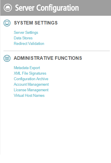
Click on Data Stores.
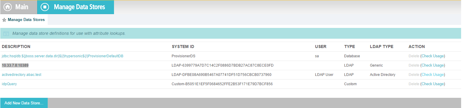
In the Manage Data Stores window, click Add New Data Store.
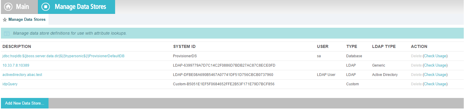
Choose LDAP, and click Next.
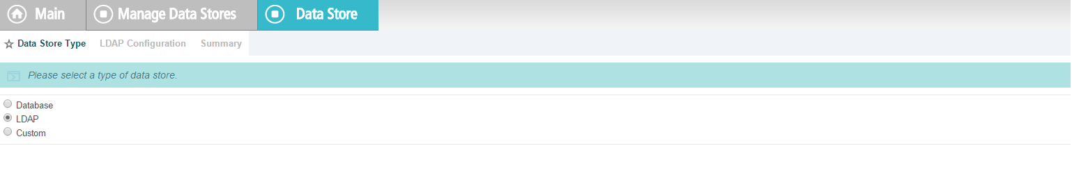
Provide a Hostname and Ldaptype.
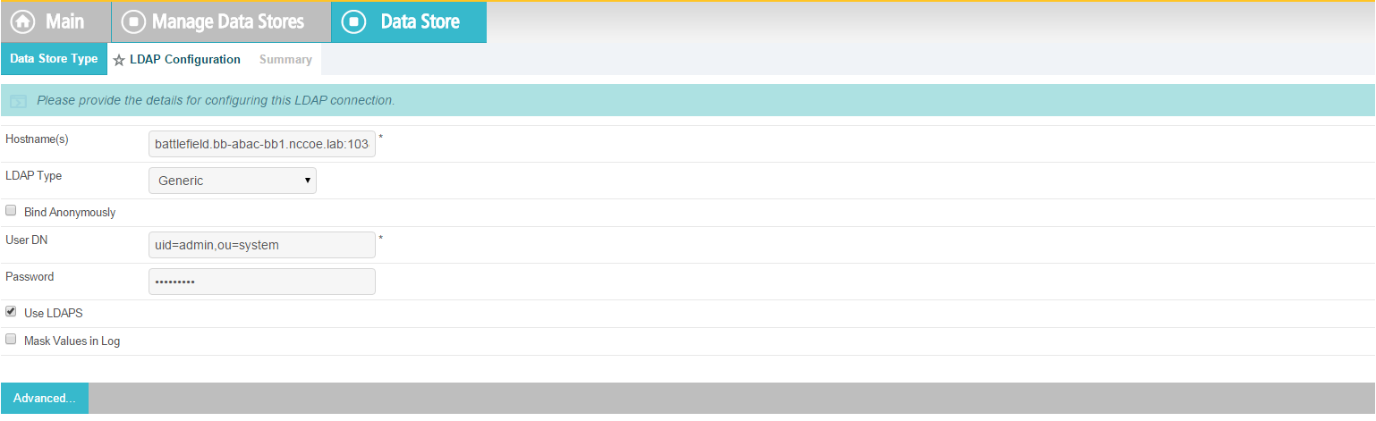
It may be necessary to configure connection pooling. It is important to select Verify LDAPS Hostname if the directory server certificate is bound to a hostname, and this hostname can be verified.
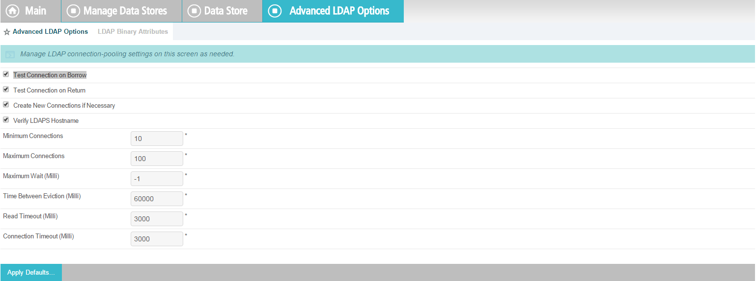
If there is any binary data, enter it in the Binary Attribute Name Field, and click Add.
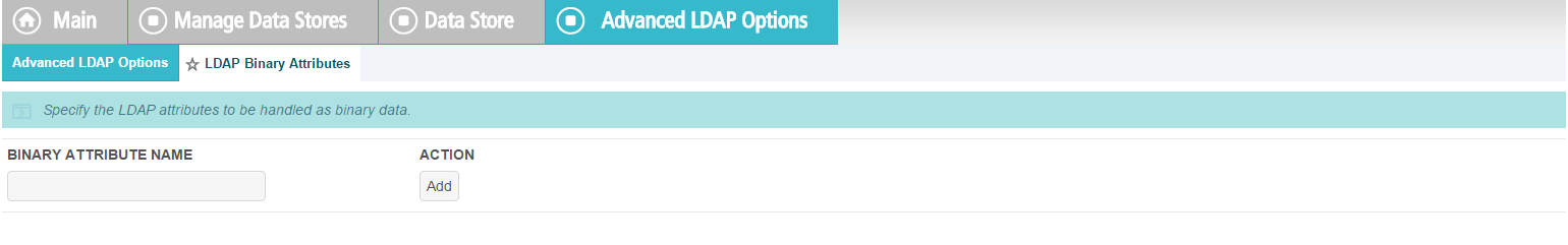
A summary of the LDAP configuration will appear.

A Summary of the connection will appear as following. Click Save. You will then return to the Main Admin console.

10.8. Configuration of PingFederate to Query the JIT Cache when Responding to Secondary Attribute Requests
10.8.1. Introduction
This section will cover all the configuration steps required to enable PingFederate RP to communicate with the Secondary attribute Provider and respond to its queries. The SP connection section will cover communication channel protection and message protection. To fulfill the query request from the NextLabs PIP Plugin and Protocol Broker, PingFederate queries its local LDAP server called Just in Time (JIT) cache. Note that PingFederate RP may not have data to fulfill the query. In that case, PingFederate RP extends the query to PingFederate IdP using a unique method (Ping Data source).
A Data Store is any type of source for digitized data, i.e., database, file, stream, etc. PingFederate administration console uses this term for system settings. In the Java software platform, data source is a factory for connections to the physical data source that this data source object represents. Thus, data source is the logical manifestation of a physical data store in a java application. Due to this, the terms will be used interchangeably below.
This section provides the configuration needed to query JIT cache, i.e., creation of the data source for the LDAP Server. We have already discussed the configuration of Ping Data Source in Custom Data Store section. SP connection describes how both of these data stores are chained together to fetch the result of the attribute query.
10.8.2. Prerequisites
Before starting this configuration, the following steps must have already been completed:
10.8.2.1. SP Connection
As described above, PingFederate (RP) acts as an IdP for the Secondary attribute provider. In order to enable support for exchange of federation-protocol messages and provide channel protection, it is essential to configure the SP (Service Provider) connection. Note: Ping Identity’s documentation uses the term Service Provider and SP where the rest of our ABAC documentation uses the term Relying Party and RP. In this document, please consider these terms interchangeable.
The following goals are achieved by configuration of the SP connection:
- Specification of connection and associated security protocol (i.e., TLS/SSL)
- Specification of SAML profile t including detailed security specifications (the use of digital signatures, signature verification, XML encryption)
- Specification of Attributes that may be sent using the SAML2 Attribute Query profile
- Specification of Data Store(s), if agreement between Idp and SP includes sending a SAML response containing attribute values from a local data store
10.8.2.1.1. Specification of Profile
Instructions on how to create a new connection can be found here.
Click on Manage on All SP in the first column on the left hand side.

The following screen will appear. Click on Create Connection.
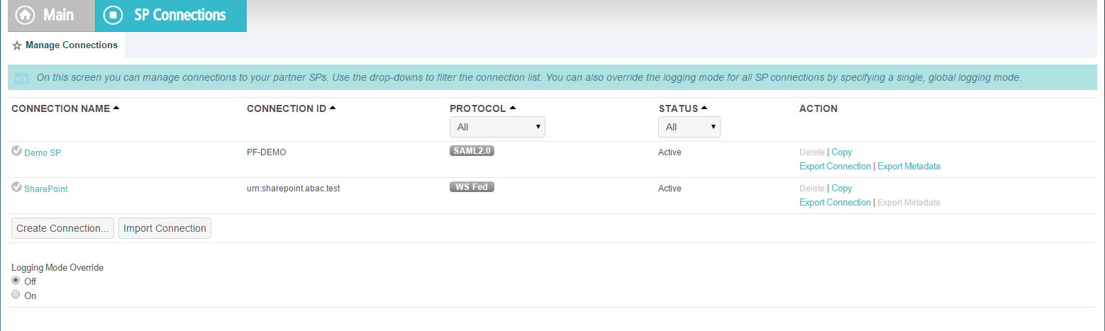
Check the box for Browser SSO Profiles and select SAML 2.0 as protocol from the drop-down menu.
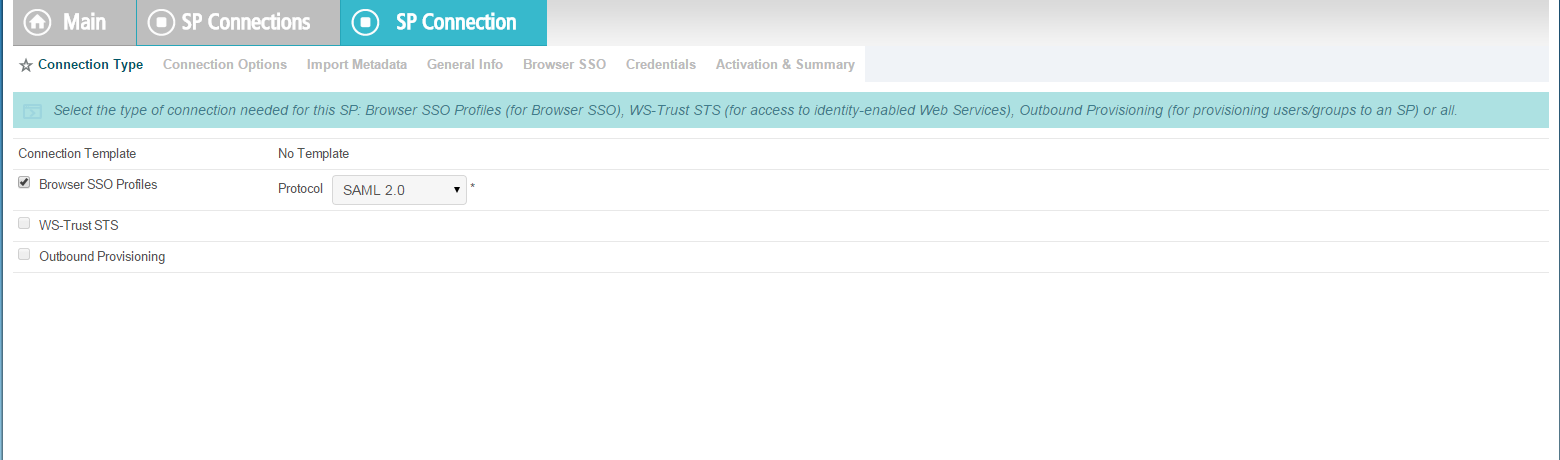
Uncheck Browser SSO, check Attribute Query, and click Next.
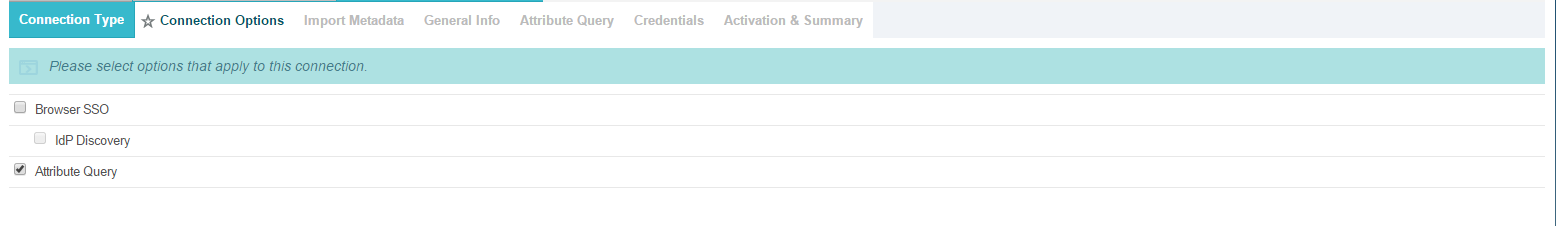
Choose a metadata file and click Next.
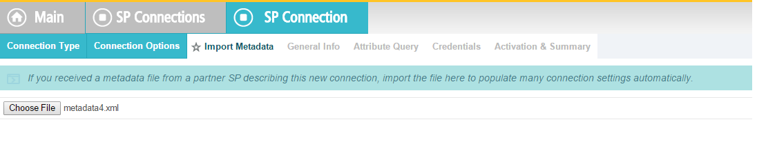
SAML2 metadata has its own specification. As per this specification, KeyDescriptor is an optional sequence of elements that provides information about the cryptographic keys that the entity uses when acting in this role. However, for message authentication and integrity, it is essential to provide the certificate so that signed messages coming from the secondary attribute provider can be verified. A relevant part of metadata is shown here:
<md:KeyDescriptor use="signing">
    <ds:KeyInfo>
        <ds:X509Data>
            <ds:X509Certificate>
                MIIE4jCCAsqgAwIBAgICEAMwDQYJKoZIhvcNAQELBQAwYjELMAkGA1UEBhMCVVMx ETAPBgNVBAgMCE1hcnlsYW5kMRIwEAYDVQQHDAlSb2NrdmlsbGUxDjAMBgNVBAoM BU5DQ29FMQ0wCwYDVQQLDARBQkFDMQ0wCwYDVQQDDARBQkFDMB4XDTE1MDQwMTE4
                MTA1NloXDTE2MDMzMTE4MTA1NlowejELMAkGA1UEBhMCVVMxETAPBgNVBAgMCE1h cnlsYW5kMQ4wDAYDVQQKDAVOQ0NvRTENMAsGA1UECwwEQUJBQzEUMBIGA1UEAwwL TU0xOTU1OTItUEMxIzAhBgkqhkiG9w0BCQEWFHNqaGFATU0xOTU1OTItUEMub3Jn
                MIIBIjANBgkqhkiG9w0BAQEFAAOCAQ8AMIIBCgKCAQEAuzxrL5iAIpNyEXHmGTDW 1mzx7YJal/c9Ruxag3sifjzuUdBjEznFJJxaagM2pzTUI5JCaLzgm71VSBmuVL+6 PzTxReM3i5XzWjpgRMIizadnQT0wmCryKuNaQiBIFLoMbi+ySdBvu+M/xhHlRxuF
                jY9NPSE1MHL8YaLoKW2SFIm/3bhJ/xF7q7FGHMcJH4Zzr2QpQmBEryozJJV3z4Zv Vro/MfyLg1VER0pu36e32hIyzsf2gKizv00qY2ecDlBCNTITsA2HWSTf50kpvT4q upCnXVKVqzDPZON0XCsJJcwWsUi9pRvkGtVBXqhh282ODyzcl3nkpgsl5F8hR7kO
                jQIDAQABo4GJMIGGMAkGA1UdEwQCMAAwCwYDVR0PBAQDAgXgMCwGCWCGSAGG+EIB DQQfFh1PcGVuU1NMIEdlbmVyYXRlZCBDZXJ0aWZpY2F0ZTAdBgNVHQ4EFgQURPRr 8BNghnDip40B1sy6AWpWJmcwHwYDVR0jBBgwFoAUyZ5WFPtCW/BOjVxvof8eNcBo
                5c8wDQYJKoZIhvcNAQELBQADggIBAGhVMd47uFNi1z8oEYgwDInZDAtfujvkfTu2 Dtr7dvkvB2x6uW481ffIKDKb48yKVBMO0kSwU4esPHgMWowJJs37XFo9PYJ1kaE/ NCD7e8V4p3xhzXux6JqKpaho1xHifzEsdKqOyNj00ZXqmRMstbw6UC+IFCNUWJZQ
                zJ+Dwciaxa9kq/huv8BMbYzcL8r1fE3x9nUwwwuFuXudpnED0B+Rmmod1G5fVG1j agMWakXscGJ9rpT8wgfJGjU4Sct3Eocp5roRGopUVBrW6jljZD4dYEu1eJ1LJqcW mDiYdZIvu0z393HApNpwC4XSaMoTN7xq4Z+Xwe0zdt1HVM0aeAiglrDB3XKuiYQT
                Ab899WBgK/TixTLJ+Nf6FkAl2apkVkaxxl+35DZrkDOHo3HQTORQFNYcb1LlrsfP A5r0PPVi6XE6h4k9/CgO03Q6fzpgl7avCrw8s1m/WnmQjfc0K+op7l7zsYrnsxdB wQsnaT6GX2csy99jOpfLKlSh6jaIuFdRPMEwjhNyqTy2xoLfuYK5bxMzlpfaoZEs
                sVURPCFiC0G97xn8ffjjhv5Kby8JIRWV2QhXicf5FsWoiWZIHtHo0L9WEQXKPTO1 +831OxJDW6bosdNww8IbRft1MYqGWYCTnwmBshURCXSJrjpE/MInE5nw/7QWA/OR U3r4Pv6s
            </ds:X509Certificate>
        </ds:X509Data>
    </ds:KeyInfo>
</md:KeyDescriptor>
Verify the metadata content.
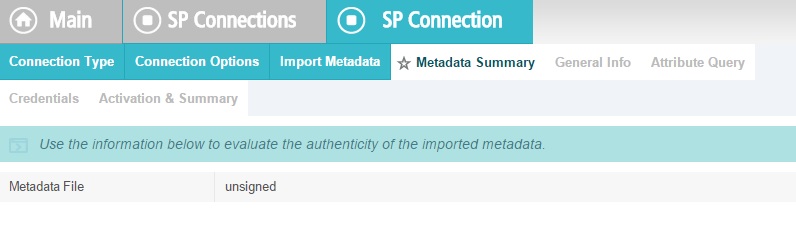
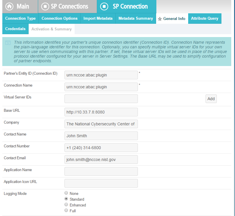
Click on Configure Attribute Query Profile.
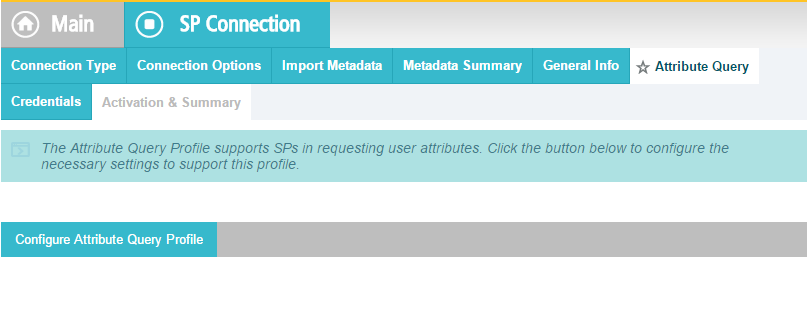
Specify the list of attributes that may be returned to the SP in response to an attribute request.

10.8.2.1.2. Specify a series of data stores.
In the Attribute Source Id field, specify JIT (LDAP).
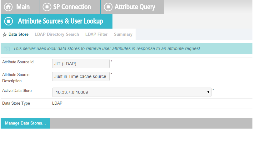
Specify Attributes for the JIT Cache.
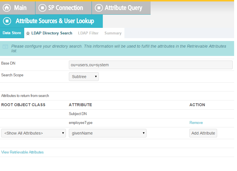
Specify LDAP Filter.

Verify that your data is correct.
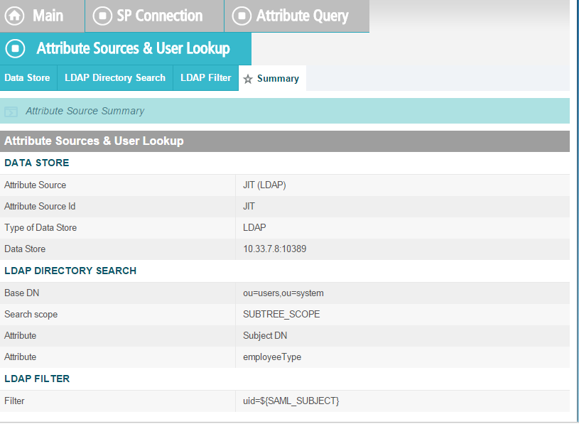
Specify a custom Data Store.
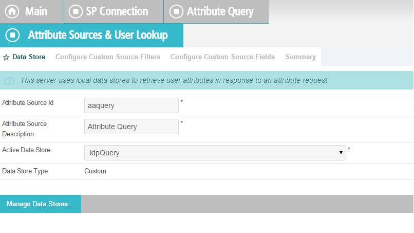
Define a filter for extracting data from this data store.
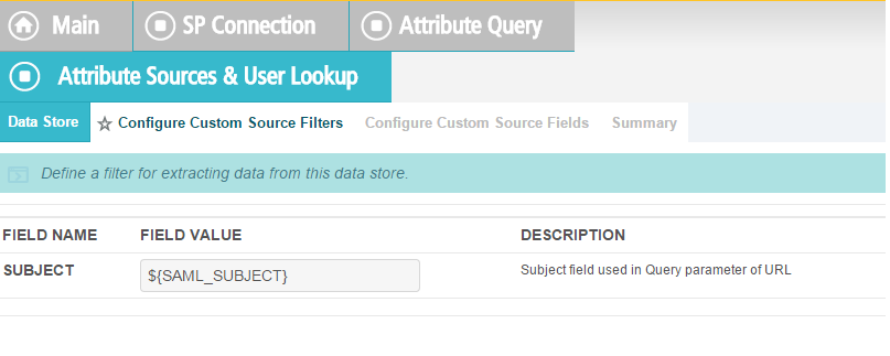
Based on the data elements available from this data store, select the ones pertinent to this connection. Note that these are the attributes you previously selected to return from Ping Custom Data.
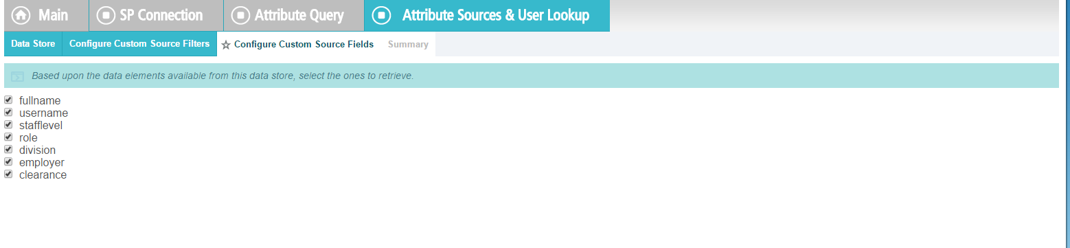
Click Retrieve.

Click on Attribute Mapping Fulfillment.
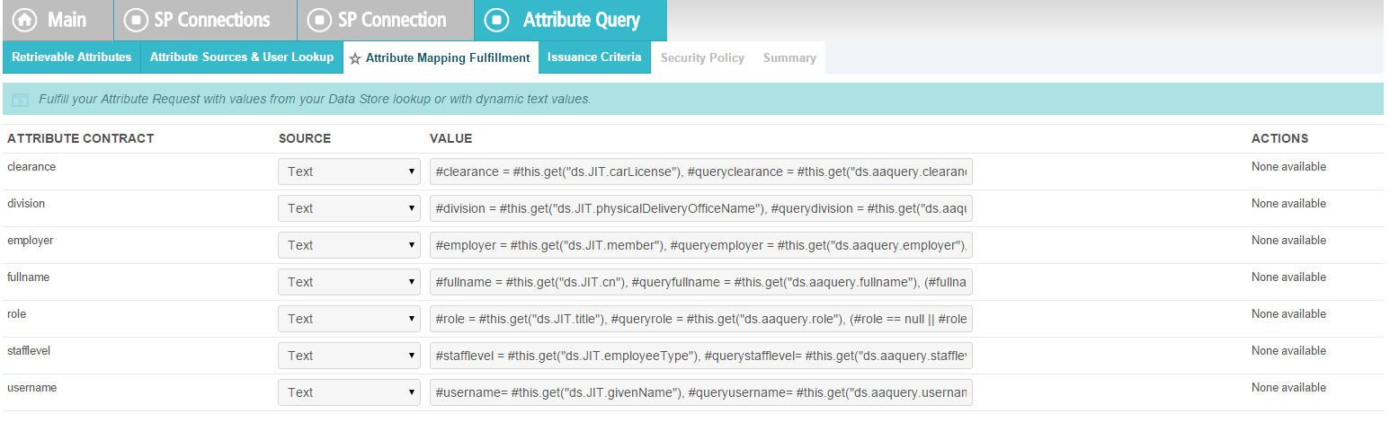
Issuance Criteria: PingFederate can evaluate various criteria to determine whether to issue an attribute query response. Use this optional screen to configure the criteria for use with this conditional authorization.
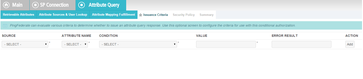
Click on Security Policy.
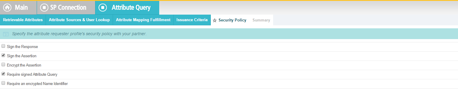
Check the Summary.
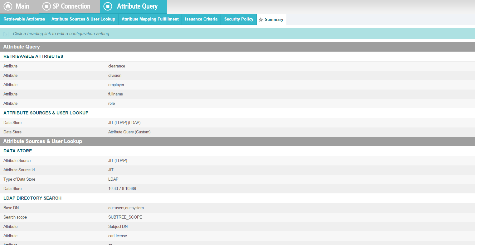
Provide Credentials for the back channel attribute request.
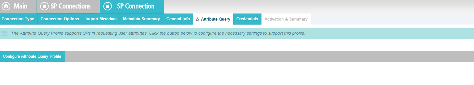
Specify Inbound Back-Channel Authentication and Digital Signature on the message.
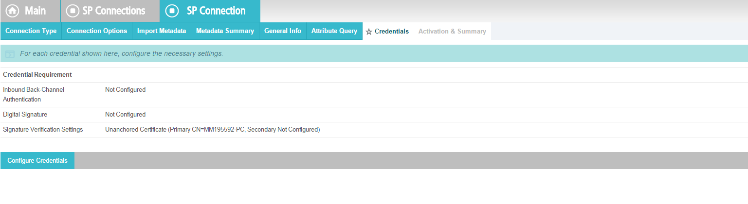
10.8.2.1.3. Back Channel Authentication Configuration
Use the default Transport Layer Authentication with SSL Client Certificate.
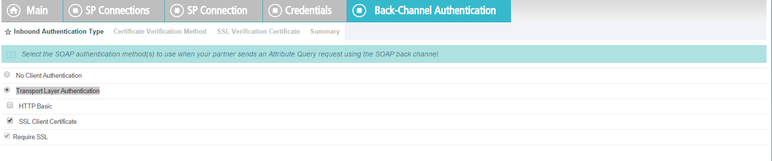
It is encouraged to use the Anchored verification method.
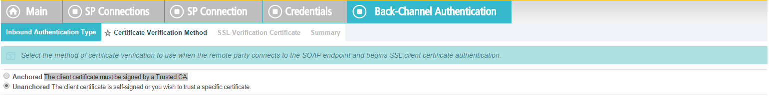
You will be prompted to select an SSL Verification Certificate. In our build, a certificate has not been previously imported. Click on Manage Certificate.

Click Import.
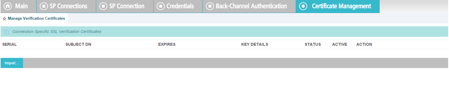
Click Choose File.
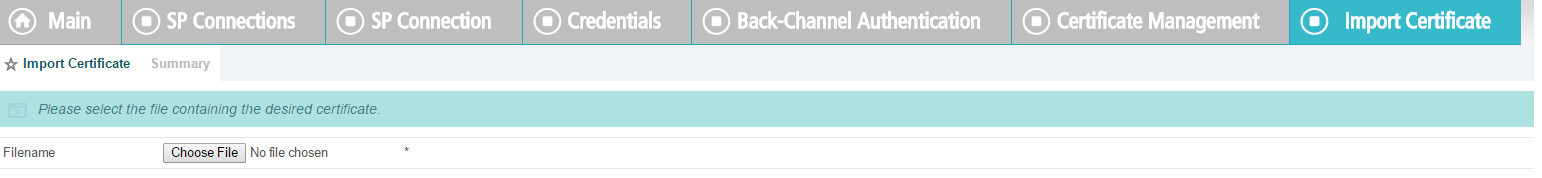
Select your certificate file from the Explorer window.
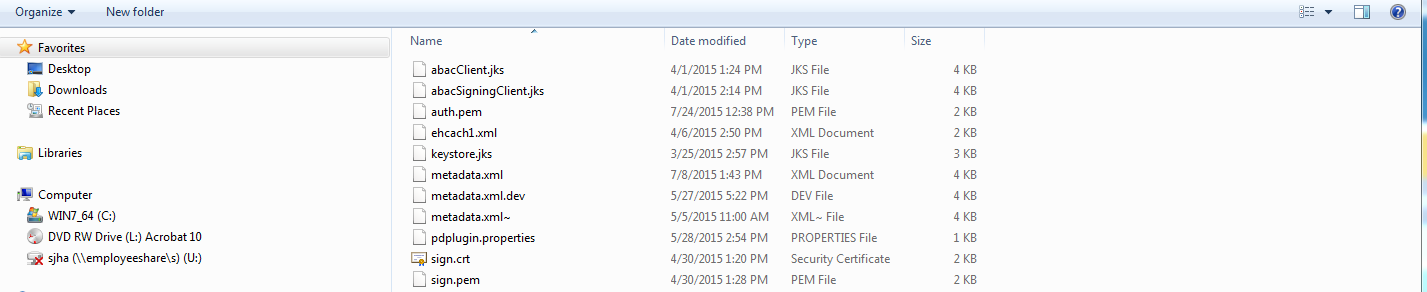
The file name will appear in the Filename field.
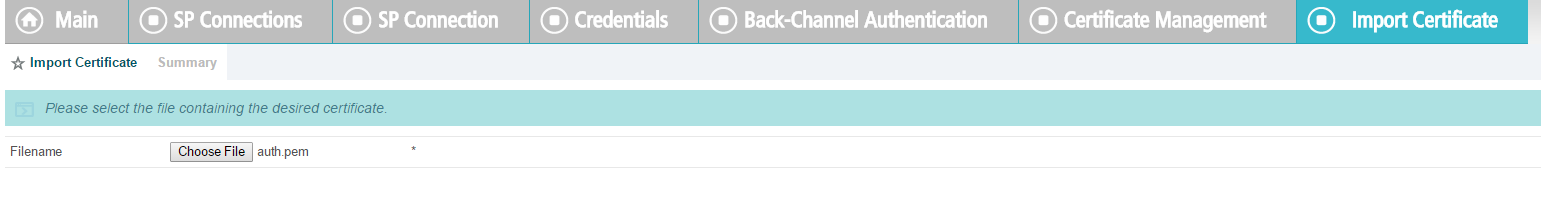
Click Next. This will display details of parts of certificate.
Check Make this the active certificate and click Done.
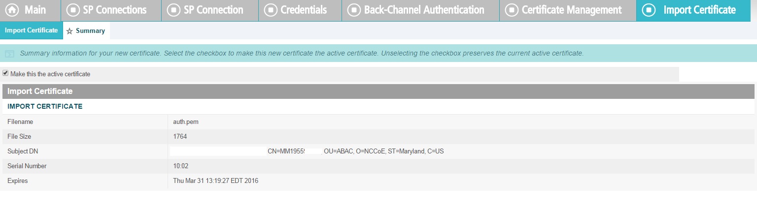
Verify the certificate.
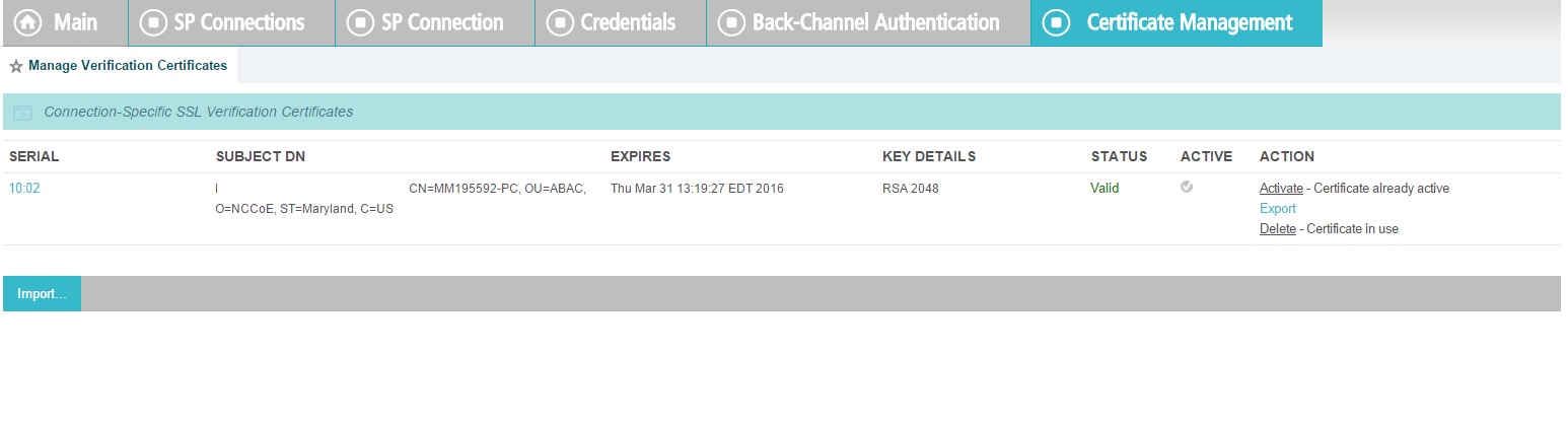
Under Action, select Activate.
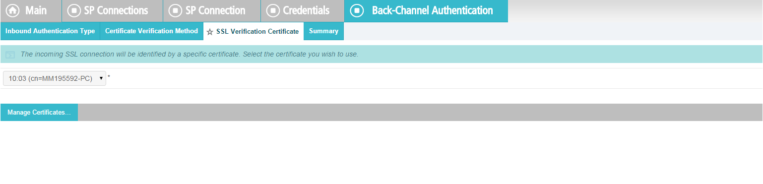
View a Summary of the verification.
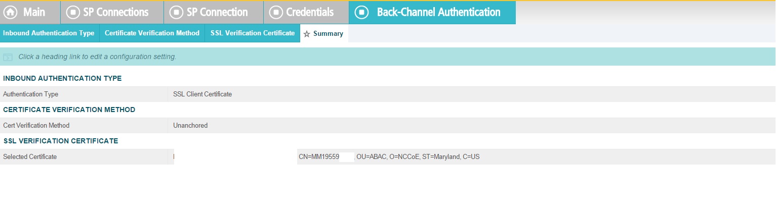
Return to the Back Channel Authentication tab.
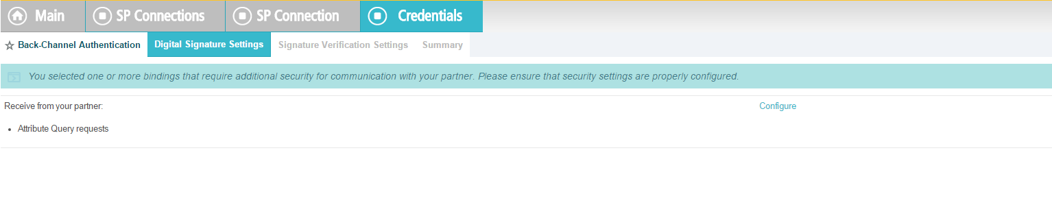
Select Digital Signature Settings for outgoing messages, then click Next.
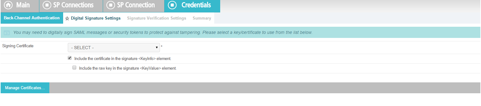
Go to Digital Signature settings. Click Configure.
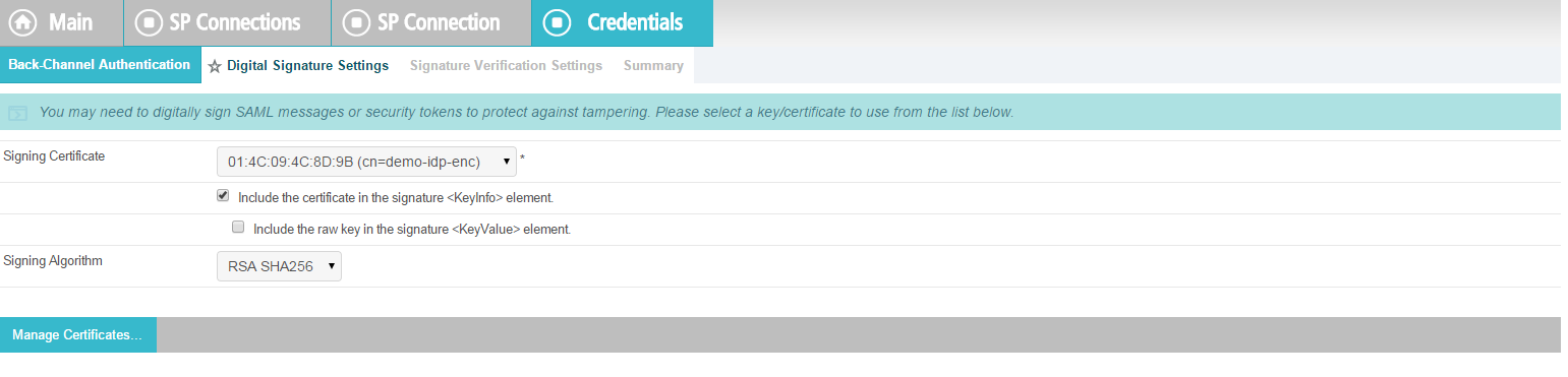
Select Digital Signature Settings on incoming messages.
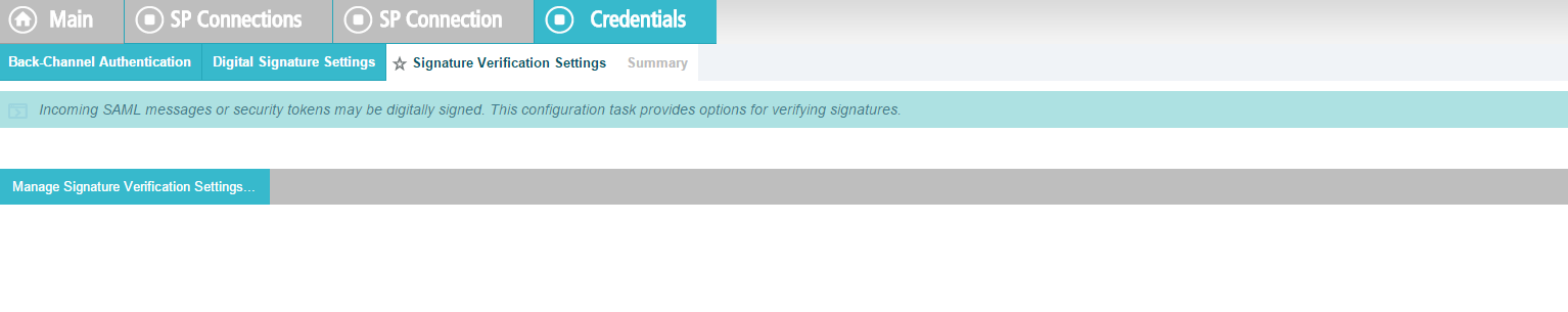
Click on Manage Signature Verification Settings.
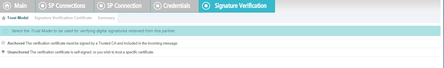
Select the certificate(s) to use when verifying these digital signatures. When multiple certificates are chosen, each certificate is tried from the top of the list down until the signature is verified. It is assumed that signed certificates have already been imported. If not, click on Manage Certificate and complete the steps detailed earlier for importing a certificate.
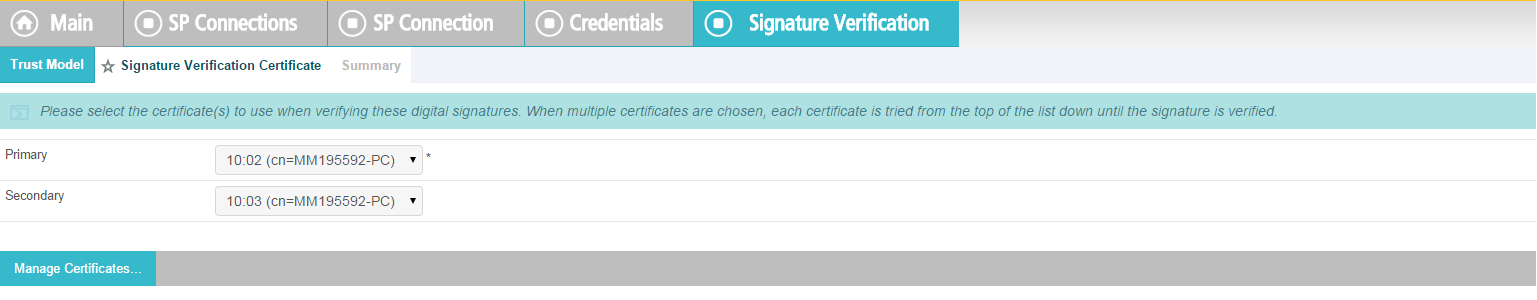
Verify the Summary.
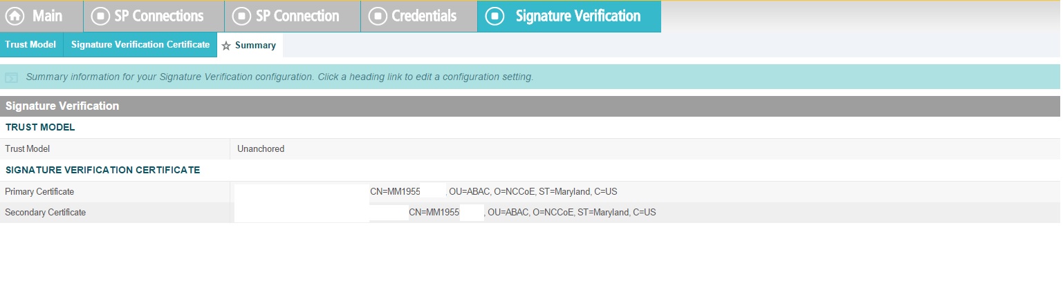
This completes the signature verification credential settings.
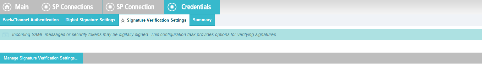
Verify the Summary.
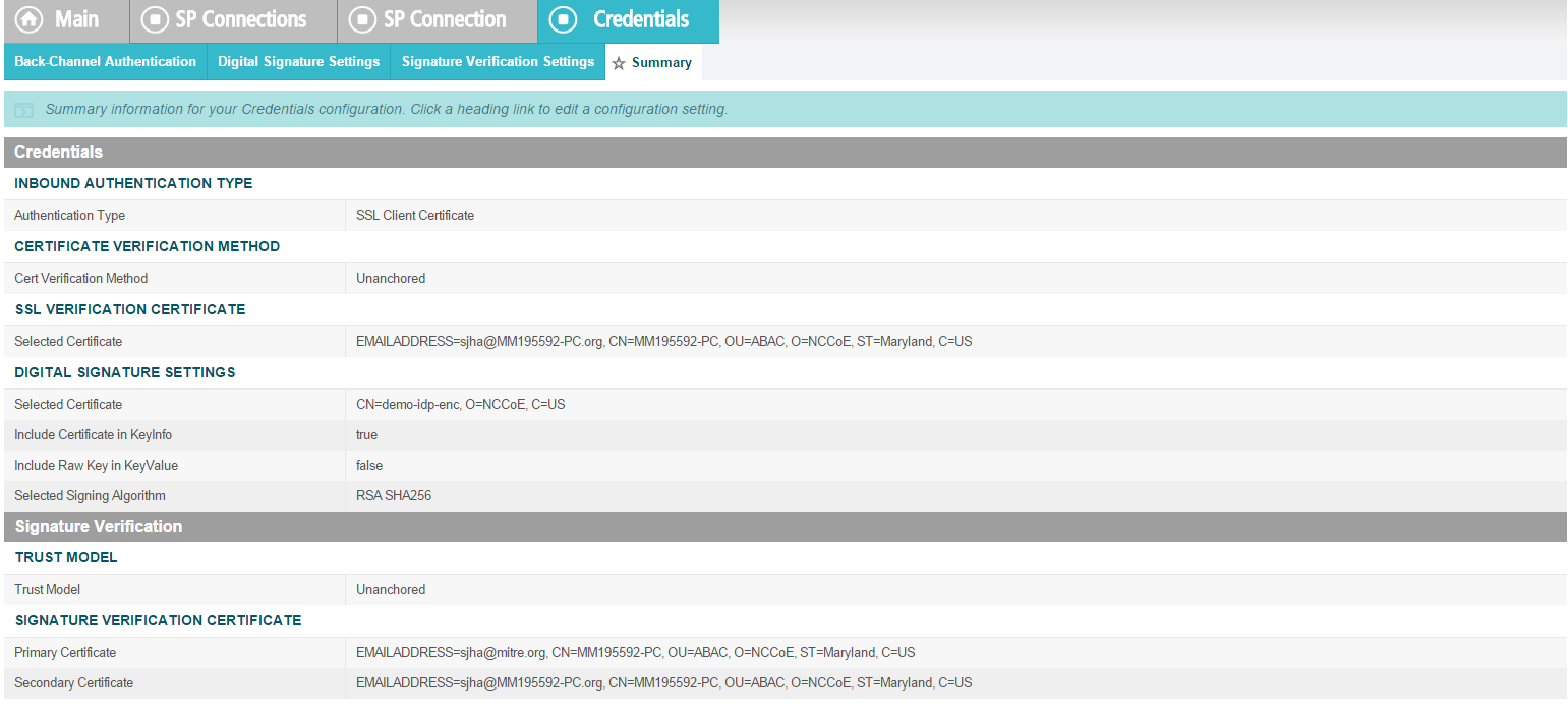
Activate the connection and Save.
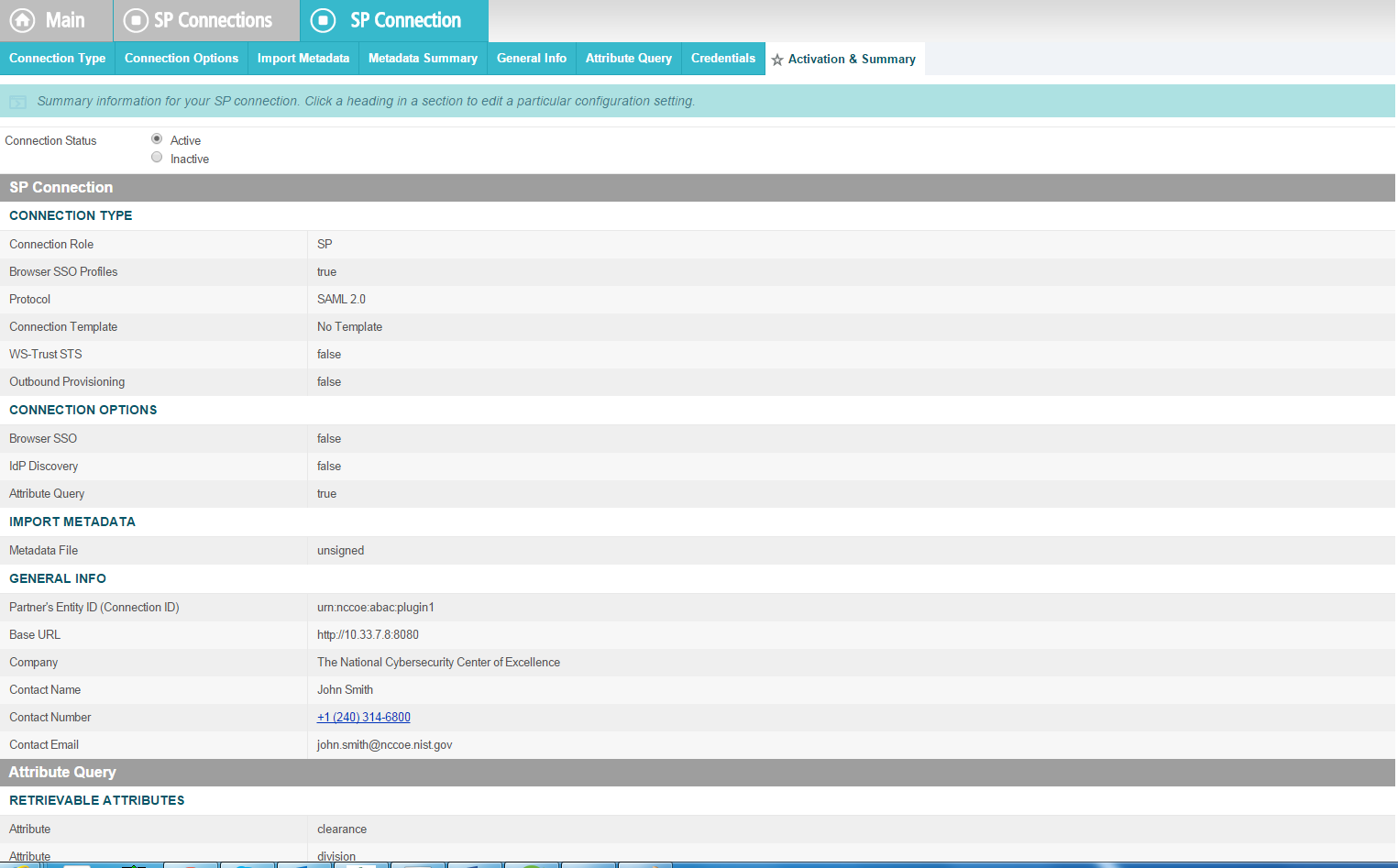
Save again.
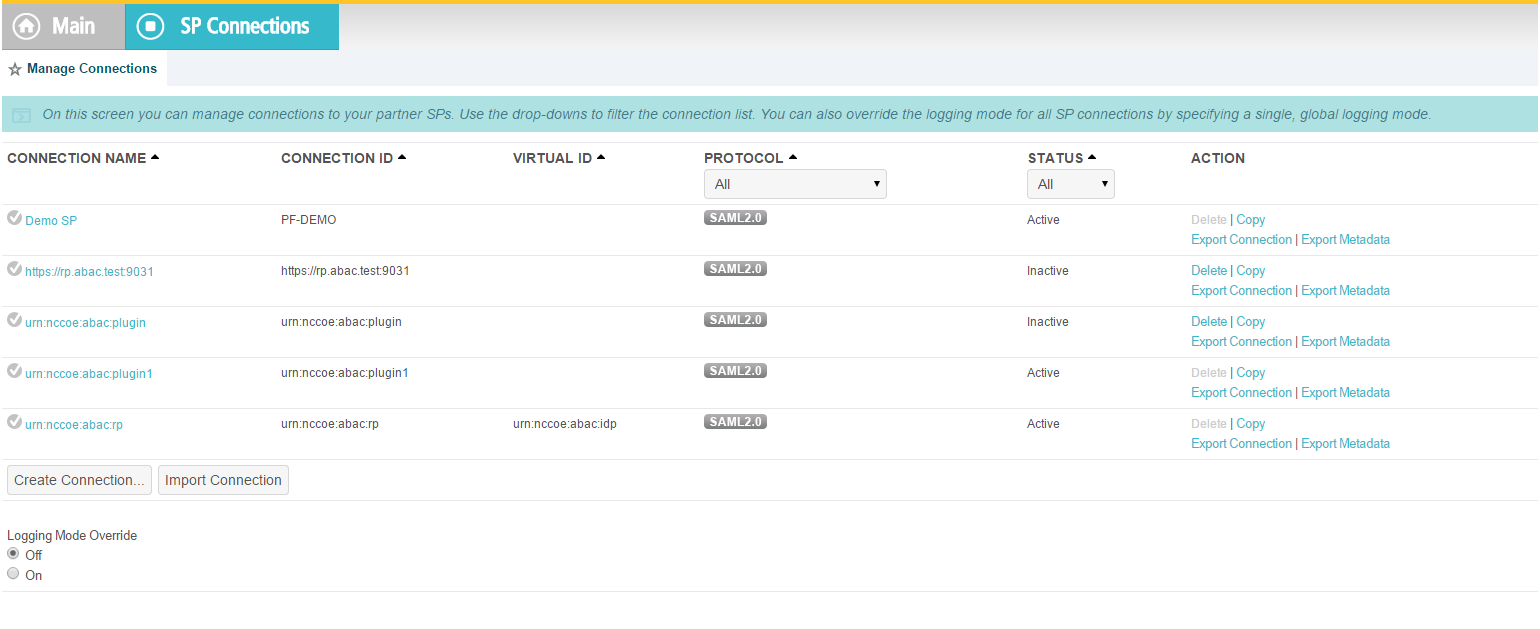
10.8.2.2. IDP Connection
As an SP, you are making a connection to a partner IdP. Follow these steps to select the type of connection needed for this IdP:
On the right hand side of the administrative console, click Manage All IdP under IdP Connections.
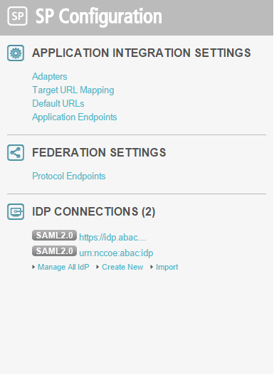
Open the connection that was created in Section 6. Click on Connection Option. It my default to Browser SSO. Additionally, select Attribute Query and JIT Provisioning.
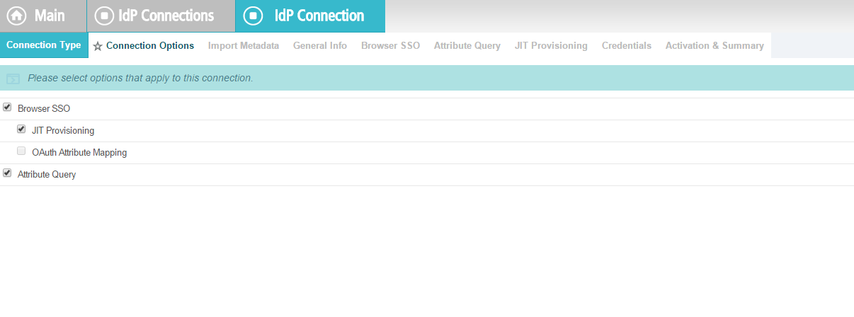
Click Next. Verify that the information in the General Info tab is correct.
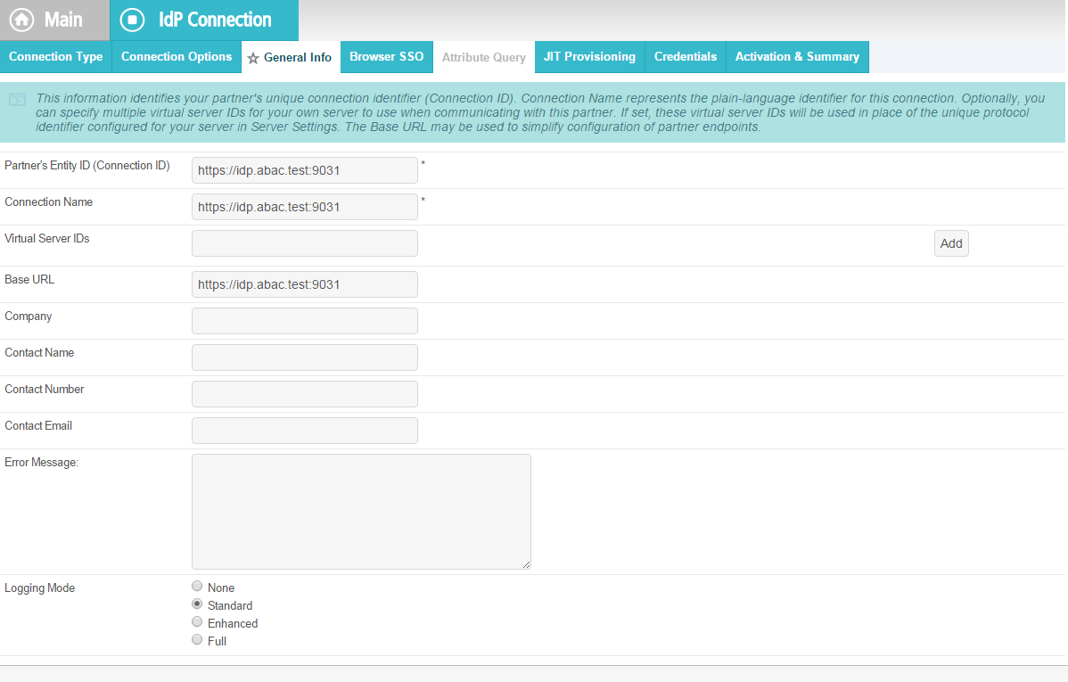
Click Next.
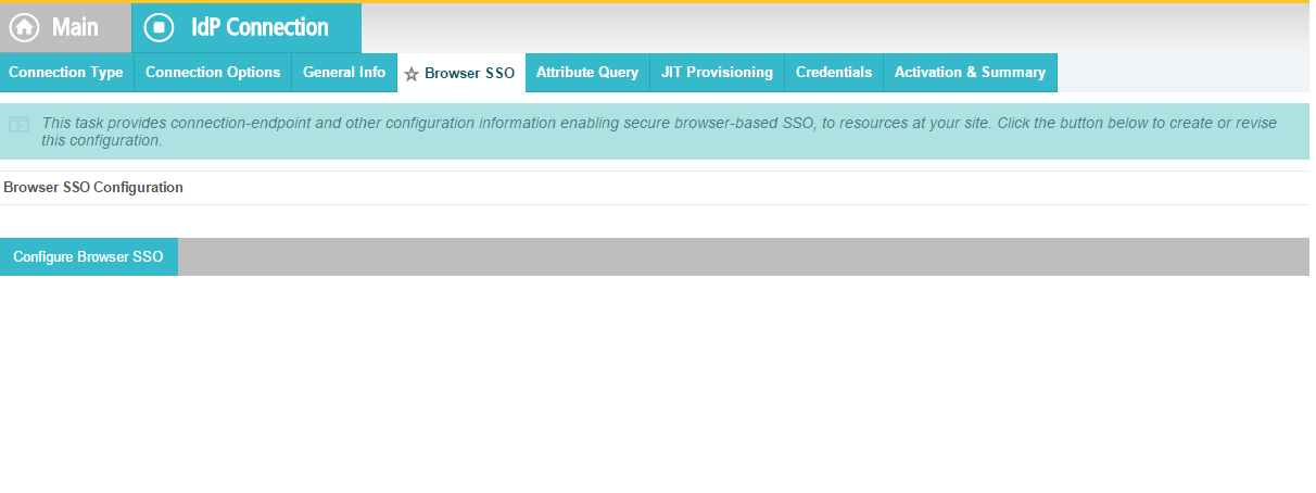
Click on Configure Attribute Query Profile.
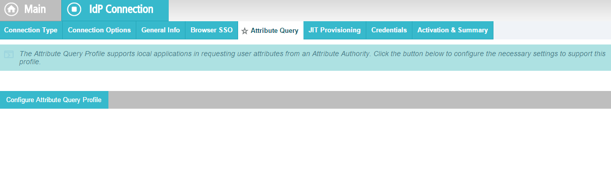
Specify an Attribute Authority Service URL.
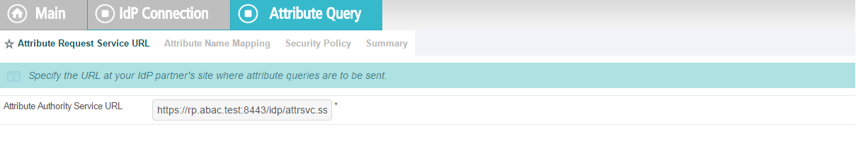
Attributes requested by your application may not match exactly the attributes supplied by the IdP. Specify the mapping between these sets of attributes.
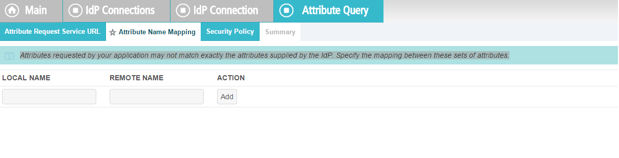
Select Sign the Attribute Query.
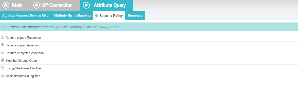
Verify that the Summary is correct, then click Done.
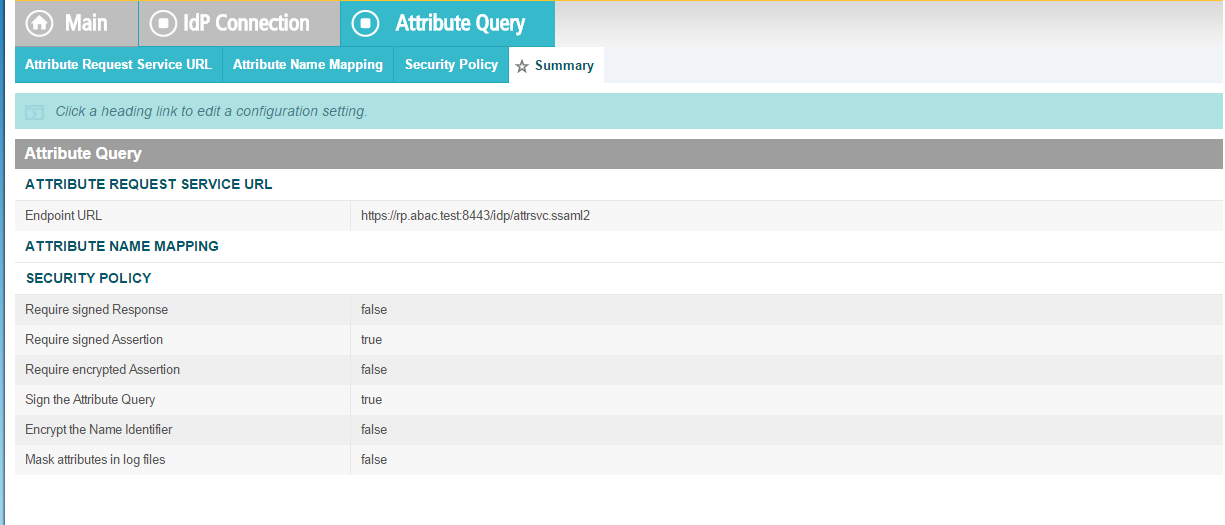
When the following screen appears, click Next.
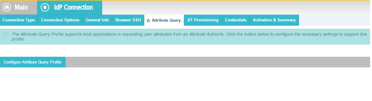
JIT provisioning details have been provided by PingFederate here.
Save the configuration.
Select Application Authentication.

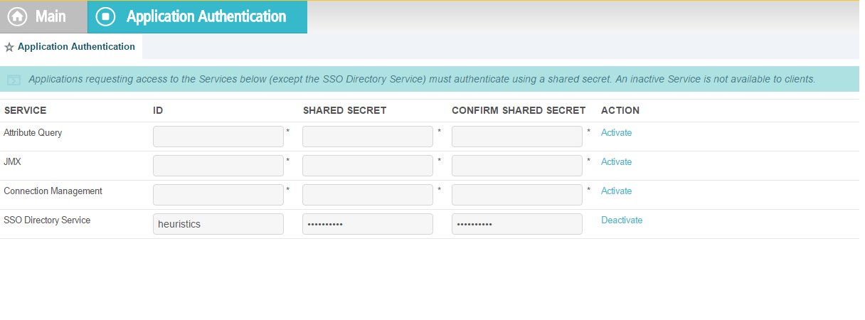
Enter appid in the ID field, and use the shared secret that you input during custom data store configuration, then save the configuration.
Select Browser SSO and Attribute Query.
10.9. ApacheDS Schema Extension
At a high level, LDAP Schema is the collection of attribute type definitions, object class definitions, and other information which a server uses to determine how to match a filter or attribute value assertion (in a compare operation) against the attributes of an entry, and whether to permit add and modify operations. For a more formal definition, look into Section 4.1 of RFC 4512.
ApacheDS comes with a comprehensive set of predefined, standardized schema elements. Specification of many of these elements can be found in RFC 4519. Generally, these predefined schema satisfy most of the needs of a project. However, you may sometimes be required to define additional attributes or object classes that are not included in the server provided schema.
Each attribute and object class has an associated unique Object Identifier. Generally, An Object Identifier is a tree of nodes where each node is simply a sequence of digits. The rules roughly state that once an entity is assigned a node in the Object Identifier (OID) tree, it has sole discretion to further delegate sub-trees off of that node. Some examples of OIDs include: 1.3.6.1 - the Internet OID, 1.3.6.1.4.1 - IANA-assigned company OIDs. It is formally defined using the ITU-T’s ASN.1 standard, X.690.
The IANA OID registry contains a list of registered entities that use OIDs to reference internal structures. In this section, we have used OIDs that are not registered anywhere. For this reason, we are using the subtree 2.25, as per recommendation by ITU. UUID is generated by the program found here.
In the following section, we will demonstrate how to create an attribute. Similar procedures can be used to create many attributes and object classes.
10.9.1. Pre-Requisites
For Schema extension, this project used ApacheDS studio. ApacheDS installation and configuration is detailed in Section 10.6 of this guide.
10.9.2. Procedure
Start ApacheDS Studio from the Start menu.
The following screen will appear:
Select File > New.
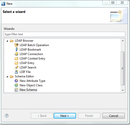
Select the New Schema Project wizard.
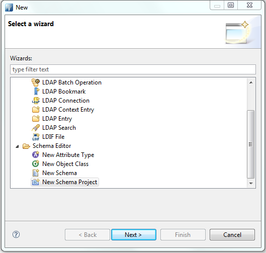
Specify a Project name, i.e., nist.nccoe.abac in our build.
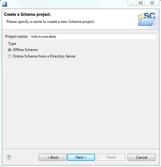
Select Offline Schema, then click Next. On the next screen, Choose the ‘core’ schemas to include.
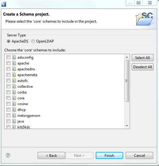
Click File > New and select New Schema.
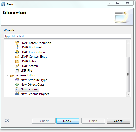
Specify a Schema name, i.e., nist.nccoe.abac in our build.
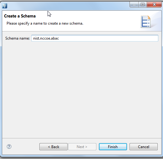
The following screen will appear:
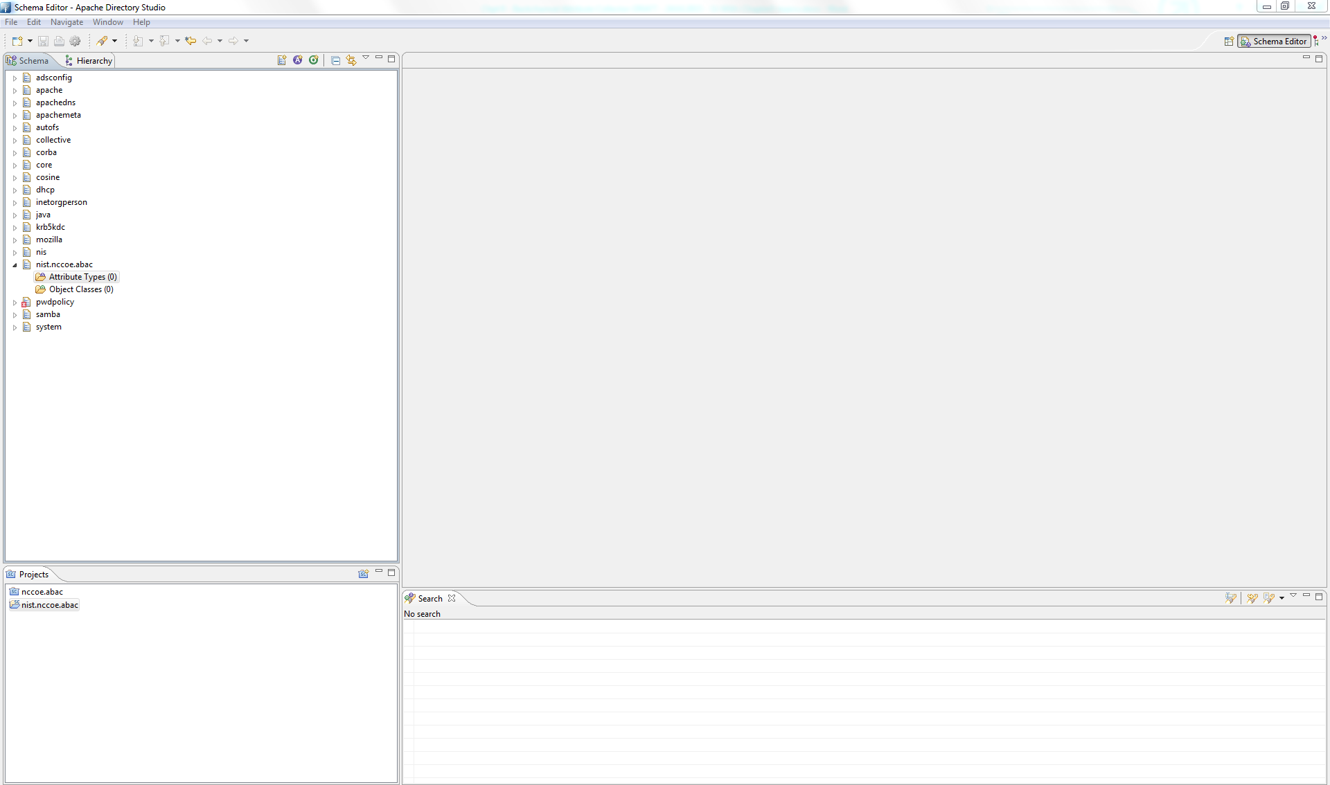
Select Attribute Types > New > New Attribute Type.
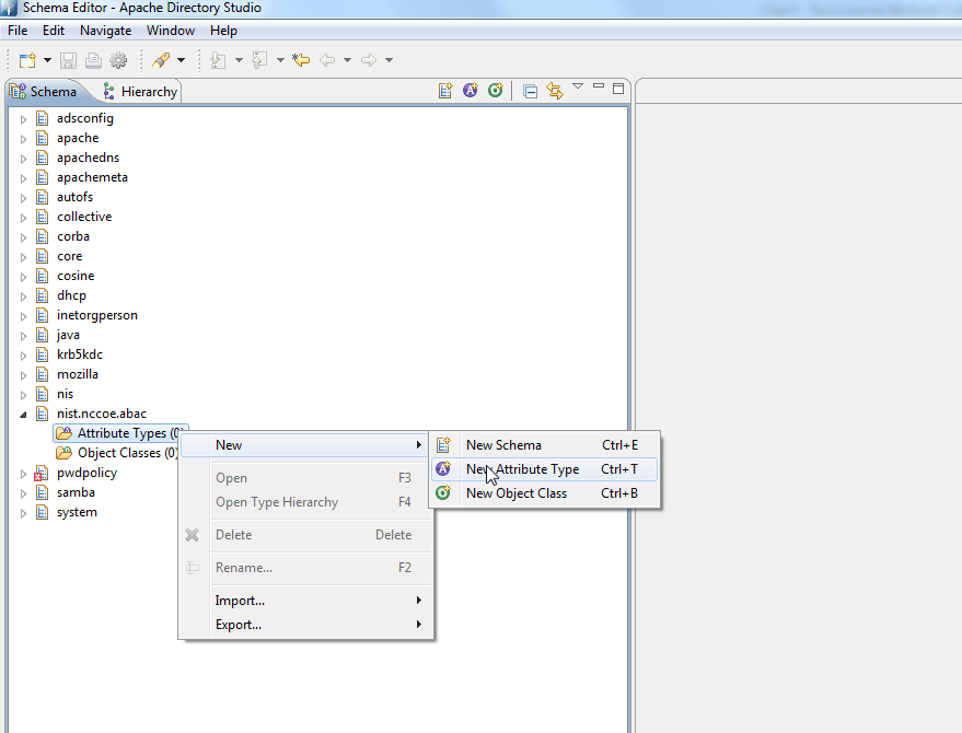
In the new window, choose the OID from the previous instructions.
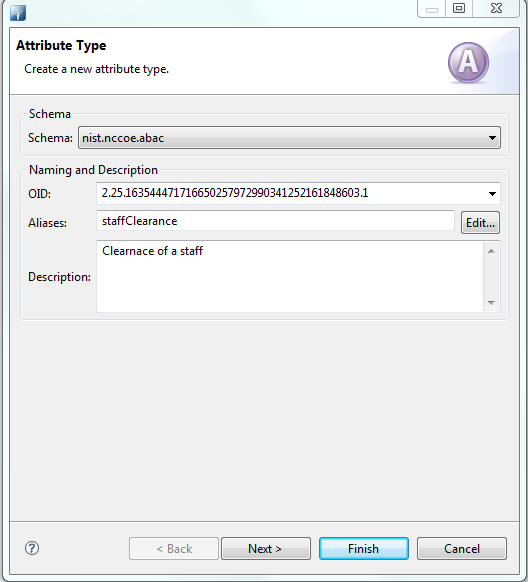
Click Next to choose the superior type of this attribute.

Specify Matching Rules. Since it is a string, case insensitivity is chosen in our build.

The following screen will appear:
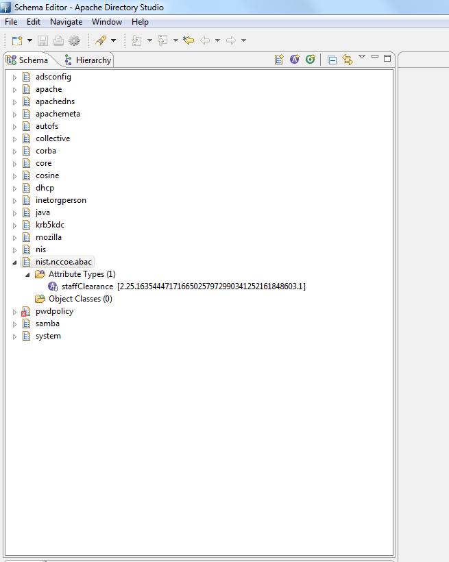
You can create other attributes by following process described above.
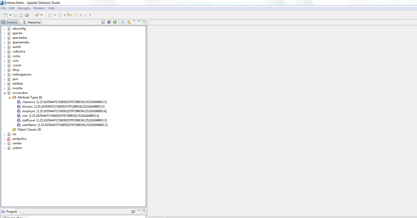
Export the schema by selecting Export > Schemas for ApacheDS. It will create an LDIF file.
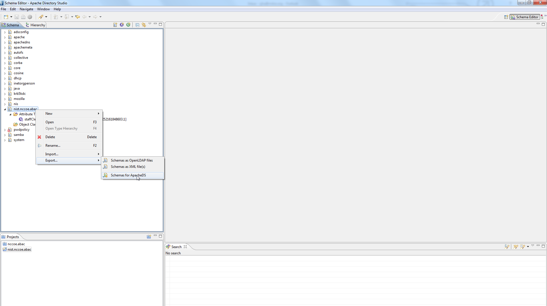
LDIF files are specified by their own RFC. In a text editor, it displays as following:
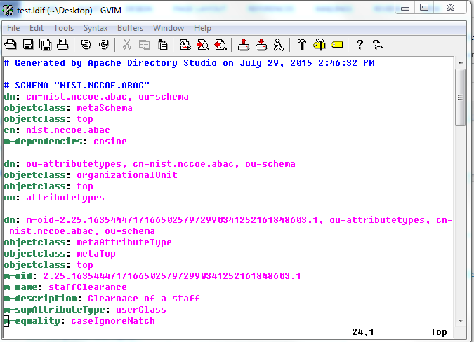
To import the file, first select Window > Open Perspective > LDAP.
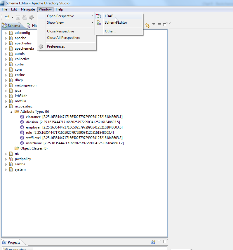
Click on the left bottom corner of the window and select New Connection.
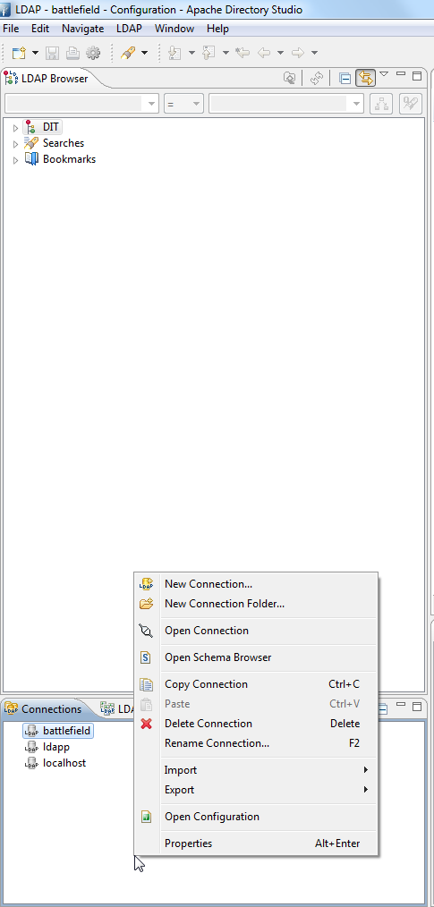
Fill in the network parameters and click Next.
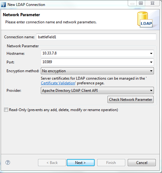
Provide credentials and click Finish.
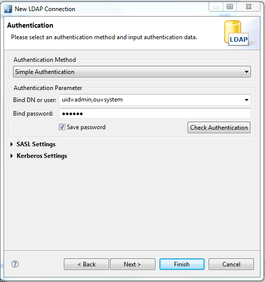
Open Schema Editor Browser and import the LDIF file created in
the previous step.
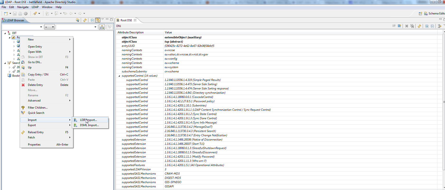
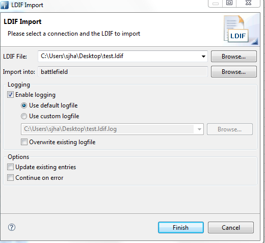
Click Finish.
To verify success, the log file generated at the end of the import should show RESULT OK.
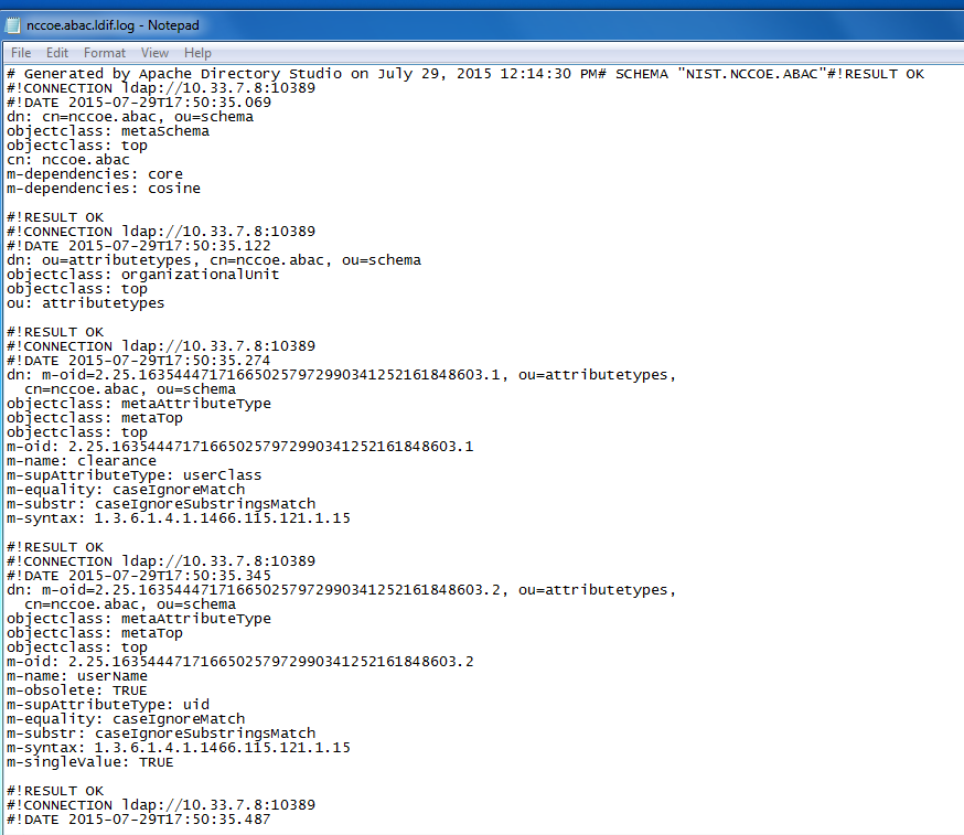
10.10. Functional Tests
Once all requirements have been met and all steps in this How-To Guide have been executed, a few functional tests will ensure that the key components of this How-To Guide were correctly deployed and are communicating with other ABAC components as desired.
The first functional test will check the ready state of the NextLabs Policy Controller (ensures that it is running after being paused for plugin deployment).
The second test will check that the plugin was successfully loaded into the NextLabs software architecture, that an attribute request is sent to the Protocol Broker from the NextLabs PIP plugin’s getAttribute() function, and that the Protocol Broker responds with an expected attribute value.
The second functional test will ensure that the Protocol Broker is successfully loaded and deployed within the tomcat server instance.
Both of these functional tests can be done on the SharePoint server.
10.10.1. Testing the Ready State of the NextLabs Policy Controller Service
Click on the Windows icon and begin typing the word Services.
When the Services application icon appears, double-click to open the Services application.
Within the Services application window, click on the Name column and look for Control Center Enforcer Service.
Verify that the status column reads Running.
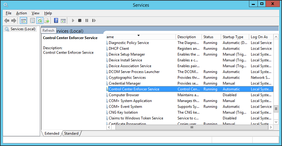
10.10.2. Test the Successful Loading of the Custom Plugin Within the NextLabs Policy Controller Software Architecture
Click on the Windows icon.
Begin typing Windows Explorer.
Click on the Windows Explorer application icon.
Navigate to C:/Program Files/NextLabs/Policy Controller/agentLog/.
Within the agentLog folder, note the Agentlog0.0 file.
Within the agentLog folder, copy and paste the locked file Agentlog0.log0 to open it for review.
- Left-click on the file name, and hold down Ctrl+C.
- Left-click anywhere in the agentLog folder, right-click and hold down Ctrl+V.
Double-click the Agent0.log-Copy.0 file to open it in your default text editor.
Within your default text editor, use a search function to search for standard NextLabs logging terminology to verify that the plugin was loaded correctly. Example:
Jul 13, 2015 4:59:21 PM com.bluejungle.pf.domain.destiny.serviceprovider.c A
FINE: Loading C:\Program Files\NextLabs\Policy Controller\.\jservice\config\nlsamlpluginService.properties
Jul 13, 2015 4:59:21 PM com.bluejungle.pf.domain.destiny.serviceprovider.c A
FINE: Loading C:\Program Files\NextLabs/Policy Controller/jservice/jar/nlsamlplugin/NLSAMLPlugin-0.0.1-SNAPSHOT-jar-with-dependencies.jar
Jul 13, 2015 4:59:22 PM com.bluejungle.pf.domain.destiny.serviceprovider.ServiceProviderManager register
INFO: A new Service 'NLSAMLPlugin_Service' is registered.
Within your default text editor, use a search function to search for logging statements you included in your plugin code to verify that the init() methods are called while the jar is loaded within NextLabs (standard according to NextLabs support). Example:
    Jul 13, 2015 4:59:21 PM gov.nist.NLSAMLPlugin.UserAttrProviderMod init
    INFO: NLSAMLPlugin UserAttrProviderMod code -- init method
    Jul 13, 2015 4:59:21 PM gov.nist.NLSAMLPlugin.HTTPSTransmitter init

You can copy and paste the locked file, or keep a live annotating
tool open that will display the contents of Agent0.log0 as new log
statements are recorded. Example from this implementation:
**BareTail by Bare Metal Software Pty Ltd.**

Example screenshot using BareTail to open the **Agent0.log0** file,
with optional highlighting illustrating evaluated policies in
yellow:

|image859|
10.10.3. Testing That the Protocol Broker .war File Loads Correctly in Tomcat Server
On the SharePoint Server, open Services, and ensure that the Control Center Enforcer Service is listed as Running.
Using Windows Explorer, navigate to your Apache tomcat installation within the Windows file structure. Example: C: /software/apache-tomcat-7.0.61
Double-click to open the bin folder. Example: C:/software/apache-tomcat-7.0.61/bin
Double-click startup.bat to start the bat, and wait for startup to complete.
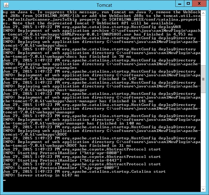
From any computer connected to this network, open an internet browser.
In the address field, type https://sharepoint.abac.test/ and press Enter.
Choose Federated Logon from the drop-down menu.
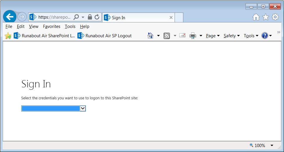
At the login screen, enter the credentials of a user that exists in your IdP Active Directory (Section 2), and click Sign On.
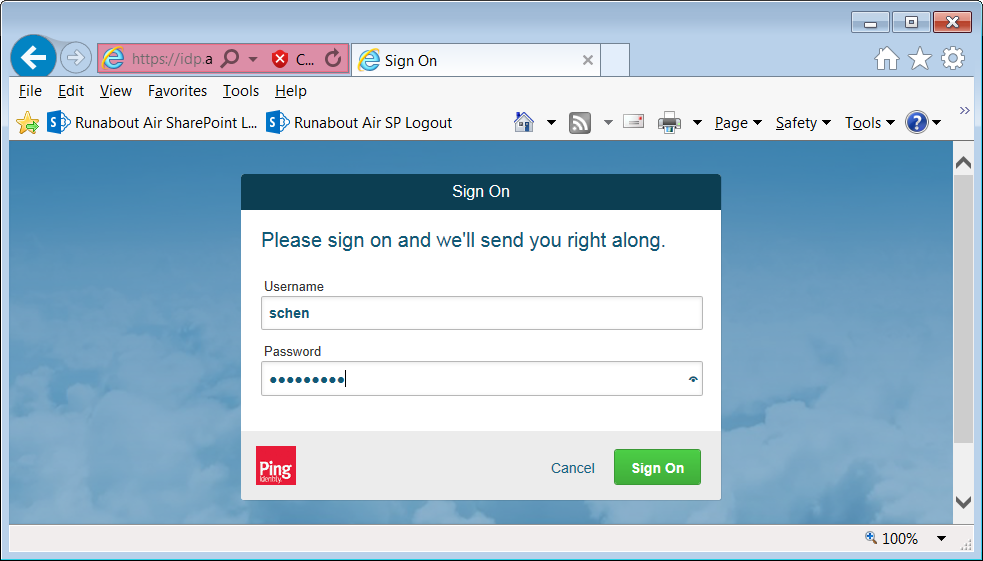
Verify that the user was able to access the main page of the RP’s SharePoint. Example:
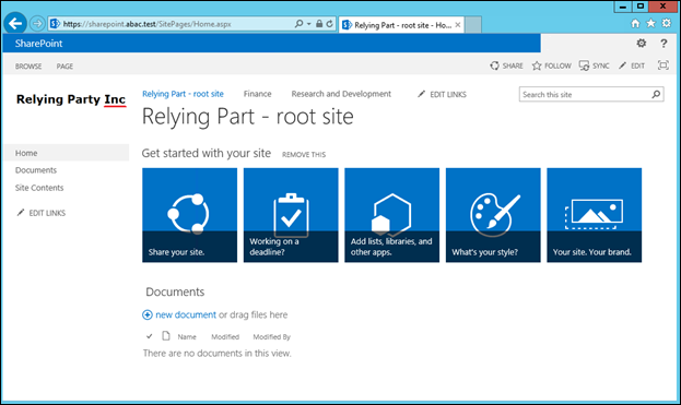
In the SharePoint site, double-click on an object for which you know the user will be missing an attribute in order to be granted access, but that can be retrieved via a secondary attribute request using the NextLabs PIP plugin, Protocol broker, and Ping custom data store.
Follow the remaining steps 15-18 to verify through standard and custom logging that the Protocol Broker was loaded, that the getAttribute() from the NextLabs PIP plugin was sent, and an expected attribute value was returned.
In Windows Explorer, navigate to your installation of Apache tomcat and locate its log files, i.e., C:/software/apache-tomcat-7.0.61/logs
Open a catalina.___.log file using your default text editor and use a search function to find standard Apache tomcat logging that indicates the .war file was correctly deployed and loads without error. For example, in C:/software/apache-tomcat-7.0.61/logs/catalina.2015-06-29.log:
Jun 29, 2015 1:49:16 PM org.apache.catalina.startup.VersionLoggerListener log
INFO: Server version:    Apache Tomcat/7.0.61
Jun 29, 2015 1:49:16 PM org.apache.catalina.startup.VersionLoggerListener log
Jun 29, 2015 1:49:16 PM org.apache.catalina.startup.VersionLoggerListener log
INFO: CATALINA_BASE:     C:\software\java\samlNewPlugin\apache-tomcat-7.0.61
Jun 29, 2015 1:49:16 PM org.apache.catalina.startup.VersionLoggerListener log
INFO: CATALINA_HOME:     C:\software\java\samlNewPlugin\apache-tomcat-7.0.61
Jun 29, 2015 1:49:16 PM org.apache.catalina.startup.VersionLoggerListener log
INFO: Command line argument: -Djava.util.logging.config.file=C:\software\java\samlNewPlugin\apache-tomcat-7.0.61\conf\logging.properties
Jun 29, 2015 1:49:16 PM org.apache.catalina.startup.VersionLoggerListener log
INFO: Command line argument: -Djava.util.logging.manager=org.apache.juli.ClassLoaderLogManager
Jun 29, 2015 1:49:16 PM org.apache.catalina.startup.VersionLoggerListener log
INFO: Command line argument: -Djava.endorsed.dirs=C:\software\java\samlNewPlugin\apache-tomcat-7.0.61\endorsed
Jun 29, 2015 1:49:17 PM org.apache.catalina.startup.HostConfig deployWAR
INFO: Deploying web application archive C:\software\java\samlNewPlugin\apache-tomcat-7.0.61\webapps\SAMLProxy-0.0.1-SNAPSHOT.war
Jun 29, 2015 1:49:22 PM org.apache.catalina.startup.HostConfig deployWAR
INFO: Deployment of web application archive C:\software\java\samlNewPlugin\apache-tomcat-7.0.61\webapps\SAMLProxy-0.0.1-SNAPSHOT.war has finished in 4,953 ms
Jun 29, 2015 1:49:22 PM org.apache.catalina.startup.HostConfig deployDirectory
INFO: Deploying web application directory C:\software\java\samlNewPlugin\apache-tomcat-7.0.61\webapps\docs
Jun 29, 2015 1:49:22 PM org.apache.catalina.startup.HostConfig deployDirectory
INFO: Deployment of web application directory C:\software\java\samlNewPlugin\apache-tomcat-7.0.61\webapps\docs has finished in 78 ms
Jun 29, 2015 1:49:22 PM org.apache.catalina.startup.HostConfig deployDirectory
INFO: Deploying web application directory C:\software\java\samlNewPlugin\apache-tomcat-7.0.61\webapps\examples
Jun 29, 2015 1:49:22 PM org.apache.catalina.startup.HostConfig deployDirectory
INFO: Deployment of web application directory C:\software\java\samlNewPlugin\apache-tomcat-7.0.61\webapps\examples has finished in 547 ms
Jun 29, 2015 1:49:22 PM org.apache.catalina.startup.HostConfig deployDirectory
INFO: Deploying web application directory C:\software\java\samlNewPlugin\apache-tomcat-7.0.61\webapps\host-manager
Jun 29, 2015 1:49:23 PM org.apache.catalina.startup.HostConfig deployDirectory
INFO: Deployment of web application directory C:\software\java\samlNewPlugin\apache-tomcat-7.0.61\webapps\host-manager has finished in 141 ms
While the same file is open, use another search function to find custom logging that indicates that the Protocol Broker was used for a SAML Attribute query request and response. Example custom log files from this build:
Jun 29, 2015 1:59:00 PM nist.pdpplugin.transport.SoapHTTPTransmitter transmit
INFO: START SoapHTTPTransmitter method. Start time: 1435600740151
Jun 29, 2015 1:59:08 PM nist.pdpplugin.transport.SoapHTTPTransmitter transmit
INFO: START SoapHTTPTransmitter method. Start time: 1435600748229
Jun 29, 2015 1:59:11 PM nist.pdpplugin.transport.SoapHTTPTransmitter transmit
INFO: END SoapHTTPTransmitter transmit Method: 1435600751682
Jun 29, 2015 1:59:11 PM nist.pdpplugin.transport.SoapHTTPTransmitter transmit
INFO: END SoapHTTPTransmitter transmit Method. Total Execution time: 11531
Within the Agent0.log0, another search function to find custom logging statements that verify from within the NextLabs Policy Controller software execution side that the plugin’s getAttribute() function was called and that the requested attribute was returned.
Example from this build:
- user: schen@abac.test
- requested attribute: clearance
- expected returned value: Secret
- actual returned value: Secret
Jun 3, 2015 11:39:17 AM gov.nist.NLSAMLPlugin.UserAttrProviderMod getAttribute
INFO: NLSAMLPlugin UserAttrProviderMod getAttribute() function called.
Jun 3, 2015 11:39:17 AM gov.nist.NLSAMLPlugin.UserAttrProviderMod getAttribute
INFO: START getAttribute method. Start time: 1433345957517
Jun 3, 2015 11:39:17 AM gov.nist.NLSAMLPlugin.UserAttrProviderMod getAttribute
INFO: NLSAMLPlugin UserAttrProviderMod getAttribute Line00-72 - subjectID param: schen@abac.test
Jun 3, 2015 11:39:17 AM gov.nist.NLSAMLPlugin.UserAttrProviderMod getAttribute
INFO: NLSAMLPlugin UserAttrProviderMod getAttribute Line00-73 - attributeName param: clearance
Jun 3, 2015 11:39:17 AM gov.nist.NLSAMLPlugin.UserAttrProviderMod getAttribute
INFO: NLSAMLPlugin Trying to check if there exist a prior entry in cache. -- UserAttrProviderMod Line00-79
Jun 3, 2015 11:39:17 AM gov.nist.NLSAMLPlugin.UserAttrProviderMod getAttribute
INFO: NLSAMLPlugin Using soapHTTPTransmitter object and calling its transmit() function.
Jun 3, 2015 11:39:22 AM gov.nist.NLSAMLPlugin.UserAttrProviderMod getAttribute
INFO: NLSAMLPlugin UserAttrProviderMod getAttribute() Line00-114 -- attributeValue returned: Secret